
1. Introduction
The ULTRICS Digital Multimeter is a compact and versatile tool designed for both commercial and home use. It functions as a voltmeter, ammeter, and ohmmeter, capable of testing continuity, AC/DC voltage, diode, transistor HFE, and car batteries. This manual provides essential information for the safe and effective operation, maintenance, and troubleshooting of your multimeter.

Image 1.1: The ULTRICS Digital Multimeter, including the main unit, test leads, and a 9V battery.
2. Safety Information
Always adhere to the following safety precautions to prevent personal injury or damage to the multimeter:
- Do not exceed the maximum input values for any range.
- Ensure the test leads are properly connected and the rotary switch is set to the correct range before making measurements.
- Avoid touching the metal tips of the test leads when connected to a circuit.
- Do not use the multimeter if it appears damaged or if the test leads are frayed.
- Always disconnect power to the circuit before measuring resistance, continuity, or diodes.
- Replace the battery when the low battery indicator appears to ensure accurate readings.
3. Product Overview
Familiarize yourself with the components and features of your ULTRICS Digital Multimeter:
- LCD Backlit Display: Provides clear digital readings, visible in low light conditions.
- Rotary Switch: Used to select the desired measurement function (e.g., Voltage, Current, Resistance).
- Test Lead Jacks: Input terminals for connecting the test leads (COM, VΩmA, 10ADC).
- Data Hold Button: Freezes the current reading on the display for easy note-taking.
- Backlight Button: Activates the display backlight.
- Built-in Kickstand: Allows the multimeter to stand upright for convenient viewing.
- Removable Rubber Casing: Provides protection against splashes and minor impacts.
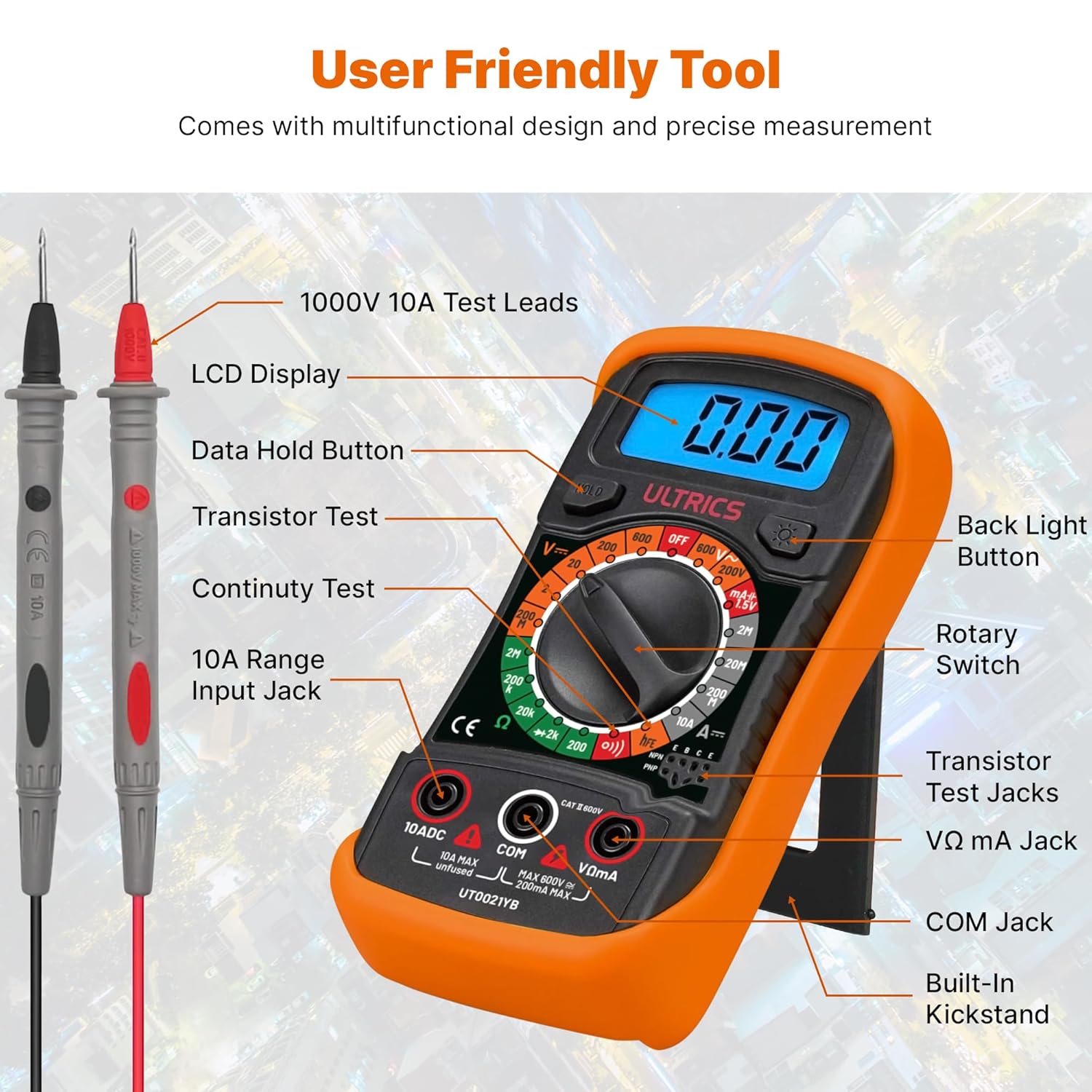
Image 3.1: Detailed diagram showing the various parts of the multimeter, including the LCD display, rotary switch, test lead jacks, and buttons.

Image 3.2: A close-up view highlighting the backlit LCD screen and the retractable kickstand for improved usability.
4. Setup
Before first use, or when the low battery indicator appears, install or replace the 9V battery.
- Battery Installation: Locate the battery compartment on the back of the multimeter. Use a screwdriver to open the cover. Insert a 9V battery, observing the correct polarity. Close the cover securely.
- Connecting Test Leads: Insert the black test lead into the 'COM' (Common) jack. Insert the red test lead into the 'VΩmA' jack for voltage, resistance, and small current measurements. For high current (up to 10A), insert the red lead into the '10ADC' jack.
5. Operating Instructions
This multimeter offers a range of measurement capabilities. Always ensure the correct function is selected and leads are connected appropriately.

Image 5.1: Visual representation of the multimeter's multi-functional capabilities, including AC/DC Voltage, Current, Resistance, Continuity, Diode, Capacity, and Transistor testing.
- Measuring AC/DC Voltage:
Set the rotary switch to the 'V~' (AC Voltage) or 'V-' (DC Voltage) range. Connect the test leads in parallel to the circuit or component being measured. Read the value on the LCD. - Measuring DC Current:
Set the rotary switch to the 'A-' (DC Current) range. Ensure the red lead is in the appropriate current jack (VΩmA for mA, 10ADC for 10A). Connect the multimeter in series with the circuit. Read the value on the LCD. - Measuring Resistance (Ω):
Set the rotary switch to the 'Ω' (Resistance) range. Ensure the circuit is de-energized. Connect the test leads across the component. Read the value on the LCD. - Continuity Test:
Set the rotary switch to the continuity symbol (speaker icon). Connect the test leads across the circuit or component. An audible beep indicates continuity (low resistance). - Diode Test:
Set the rotary switch to the diode symbol. Connect the red lead to the anode and the black lead to the cathode of the diode. The display will show the forward voltage drop. Reverse the leads to check for open circuit. - Transistor HFE Test:
Set the rotary switch to the 'hFE' range. Insert the transistor's emitter, base, and collector leads into the corresponding sockets on the multimeter. The display will show the transistor's HFE value. - Battery Test:
Set the rotary switch to the '1.5V' or '9V' battery test range. Connect the test leads to the battery terminals (red to positive, black to negative). The display will show the battery voltage.

Image 5.2: Demonstrates the 'Hold' button function, which allows users to freeze the displayed reading for convenient note-taking or collaboration.

Image 5.3: Examples of the multimeter being used for various tests, including AC/DC Voltage, DC Current, Battery, and Continuity measurements.

Image 5.4: Illustrates the versatile usability of the multimeter across different scenarios such as car battery testing, appliance repair, laboratory work, and general DIY projects.
6. Maintenance
Proper maintenance ensures the longevity and accuracy of your multimeter.
- Cleaning: Wipe the multimeter with a damp cloth. Do not use abrasive cleaners or solvents.
- Battery Replacement: Replace the 9V battery promptly when the low battery indicator appears. Remove the battery if the multimeter will not be used for an extended period.
- Storage: Store the multimeter in a cool, dry place, away from direct sunlight and extreme temperatures.
7. Troubleshooting
If you encounter issues with your multimeter, refer to the following common problems and solutions:
| Problem | Possible Cause | Solution |
|---|---|---|
| No display or dim display | Dead or low battery | Replace the 9V battery. |
| Incorrect readings | Incorrect function selected, poor lead connection, or battery low. | Verify rotary switch setting, ensure leads are firmly connected, replace battery if needed. |
| No continuity beep | Open circuit or high resistance. | Check the circuit for breaks or high resistance points. |
| Overload indication ('OL') | Measurement exceeds selected range. | Select a higher range or ensure the input is within the multimeter's limits. |
8. Specifications
Detailed technical specifications for the ULTRICS Digital Multimeter:
| Feature | Specification |
|---|---|
| Model Number | UT0021YB |
| Dimensions | 14.6 x 10 x 5 cm |
| Item Weight | 240 g |
| Power Source | Battery Powered (9V battery included) |
| Max Voltage | 1000 Volts |
| Material | Plastic |
| Special Features | DC Voltage Range, AC Voltage, Diode Check, Battery Check, Transistor HFE Check, Overload Protection on all ranges, Low Battery Voltage Indication, Data Hold Function, Removable Thick rubber casing, Fold-out stand |
| Certifications | CE, UKCA |
9. Warranty and Support
The ULTRICS Digital Multimeter comes with a 12-month warranty from the date of purchase. This warranty covers manufacturing defects and ensures reliable performance under normal use. For technical support, warranty claims, or any inquiries, please contact ULTRICS customer service through the retailer's platform or the official ULTRICS website. Please retain your proof of purchase for warranty validation.


