1. Introduction
This manual provides detailed instructions for the installation, operation, maintenance, and troubleshooting of the D-Link DGS-1510-28X SmartPro Switch. The DGS-1510-28X is a high-performance managed switch designed for business environments, offering 24 Gigabit Ethernet ports and 4 10 Gigabit Ethernet SFP+ ports for flexible network expansion and high-bandwidth connectivity.
Please read this manual thoroughly before attempting to install or operate the device to ensure proper setup and optimal performance.
2. Product Overview
2.1 Front Panel
The front panel of the DGS-1510-28X switch features all network ports, status LEDs, and a console port for local management.

Figure 2.1: Front Panel of DGS-1510-28X Switch. This image displays the front of the D-Link DGS-1510-28X switch, highlighting its 24 standard RJ45 Gigabit Ethernet ports, four 10 Gigabit Ethernet SFP+ uplink ports (labeled 25-28), and various LED indicators for power, link status, and activity. A console port is also visible on the left side.
- RJ45 Ports (1-24): 24 10/100/1000BASE-T Gigabit Ethernet ports for connecting network devices.
- SFP+ Ports (25-28): 4 10 Gigabit Ethernet SFP+ ports for high-speed uplinks or stacking.
- Console Port: RJ-45 console port for command-line interface (CLI) management.
- LED Indicators: Provide visual status for power, link/activity, and 10/100/1000 Mbps speed for each port.
2.2 Rear Panel
The rear panel includes the power input and grounding screw.
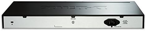
Figure 2.2: Rear Panel of DGS-1510-28X Switch. This image shows the back of the D-Link DGS-1510-28X switch, featuring the standard AC power input connector on the right and a grounding screw terminal on the left.
- AC Power Inlet: Connects to the provided AC power cord.
- Grounding Screw: For connecting an earth ground cable to protect against electrical surges.
3. Setup and Installation
3.1 Package Contents
Verify that your package contains the following items:
- DGS-1510-28X SmartPro Switch
- AC Power Cord
- Rack Mount Kit (brackets and screws)
- Rubber Feet (for desktop installation)
- Console Cable (RJ-45 to DB-9)
- Quick Installation Guide
3.2 Physical Installation
The DGS-1510-28X can be installed on a desktop or mounted in a standard 19-inch equipment rack.
Desktop Installation:
- Attach the four rubber feet to the recessed areas on the bottom of the switch.
- Place the switch on a flat, stable surface with adequate ventilation.
Rack Installation:
- Attach the two mounting brackets to the side grooves of the switch using the provided screws.
- Secure the switch into an open rack space using appropriate rack screws (not typically included with the switch).
3.3 Power Connection
- Connect the AC power cord to the power inlet on the rear panel of the switch.
- Plug the other end of the power cord into a suitable electrical outlet.
- Ensure the grounding screw is connected to an earth ground for safety.
3.4 Initial Configuration
The switch can be configured via a Web-based Graphical User Interface (GUI) or Command Line Interface (CLI) through the console port.
Console Port Connection:
- Connect the RJ-45 end of the console cable to the console port on the switch.
- Connect the DB-9 end to the serial port of a computer.
- Use a terminal emulation program (e.g., PuTTY, Tera Term) with settings: 115200 bps, 8 data bits, no parity, 1 stop bit, no flow control.
Web-based Management:
By default, the switch may obtain an IP address via DHCP or have a default static IP. Refer to the Quick Installation Guide for the default IP address and login credentials.
- Connect a computer to any of the switch's RJ45 ports.
- Ensure your computer's IP address is in the same subnet as the switch's default IP.
- Open a web browser and enter the switch's IP address.
- Enter the default username and password (refer to documentation).
4. Operating the Switch
The DGS-1510-28X is a managed switch offering a wide range of features for network control and optimization. These features are accessible through the Web GUI or CLI.
4.1 Key Features
The DGS-1510-28X supports various advanced networking functionalities, including:
- VLANs (Virtual Local Area Networks): For network segmentation and traffic isolation.
- QoS (Quality of Service): Prioritize critical network traffic for improved performance.
- Link Aggregation (LAG): Combine multiple ports for increased bandwidth and redundancy.
- Spanning Tree Protocol (STP): Prevent network loops.
- Security Features: Access Control Lists (ACLs), Port Security, DHCP Snooping, ARP Inspection.
- Single IP Management (SIM): Manage multiple switches from a single IP address.
- IPv6 Support: Ready for next-generation networks.

Figure 4.1: DGS-1510 Series Feature Overview. This image provides a comprehensive overview of the DGS-1510 series' capabilities, detailing features such as Single IP Management, various Layer 2 functionalities, Quality of Service (QoS) and bandwidth control, network security protocols, IPv6 readiness, versatile management options, and Layer 3 traffic management.

Figure 4.2: DGS-1510 Series Software Features. This image presents a table outlining the software features of the DGS-1510 series, categorized by functionality such as Virtual Stacking Support, L2 Features (e.g., MAC Address Table, Flow Control, IGMP Snooping), VLAN capabilities, Quality of Service (QoS), L3 Features, and Access Control List (ACL) capabilities.

Figure 4.3: DGS-1510 Series Advanced Features. This image details advanced features of the DGS-1510 series, including comprehensive security protocols (e.g., Port Security, DHCP Server Screening), AAA (Authentication, Authorization, and Accounting) functionalities, OAM (Operations, Administration, and Maintenance) tools, and D-Link Green 3.0 Technology for power saving.
For detailed configuration instructions on these features, please refer to the D-Link DGS-1510 Series User Manual available on the D-Link support website.
5. Maintenance
5.1 Firmware Updates
Regularly check the D-Link support website for the latest firmware versions. Updating the firmware can provide new features, performance enhancements, and security fixes. Follow the instructions provided with the firmware download carefully.
5.2 Cleaning
To maintain optimal performance and extend the lifespan of your switch:
- Ensure the switch is powered off and disconnected from the power source before cleaning.
- Use a soft, dry cloth to wipe the exterior surfaces.
- Use compressed air to clear dust from ventilation openings and ports.
- Do not use liquid or aerosol cleaners.
5.3 Environmental Considerations
Operate the switch within the recommended temperature and humidity ranges to prevent damage and ensure stable operation. Ensure proper airflow around the device.
6. Troubleshooting
This section provides solutions to common issues you might encounter with the DGS-1510-28X switch.
6.1 No Power
- Verify the power cord is securely connected to both the switch and the electrical outlet.
- Ensure the electrical outlet is functional by testing it with another device.
- Check the power LED on the front panel; it should be illuminated.
6.2 No Link on a Port
- Check the Ethernet cable connection at both ends (switch port and connected device).
- Ensure the cable is not damaged and is of the correct type (e.g., Cat5e/6 for Gigabit).
- Verify the connected device is powered on and functioning correctly.
- Try connecting to a different port on the switch or using a different cable.
- Check the port status in the switch's management interface.
6.3 Cannot Access Web Management Interface
- Ensure your computer's IP address is in the same subnet as the switch's IP address.
- Verify the switch's IP address. If unknown, use the console port for CLI access to check or configure the IP.
- Disable any firewall or antivirus software on your computer temporarily to rule out interference.
- Try a different web browser.
- If all else fails, consider performing a factory reset (refer to the full user manual for instructions, as this will erase all configurations).
7. Specifications
Below are the technical specifications for the D-Link DGS-1510-28X SmartPro Switch.

Figure 7.1: DGS-1510-28X Product Dimensions. This image illustrates the physical dimensions of the DGS-1510-28X switch, indicating a length of 17.36 inches, a width of 8.26 inches, and a height of 1.73 inches.
| Feature | Specification |
|---|---|
| Model Number | DGS-1510-28X |
| Number of Ports | 24 x 10/100/1000BASE-T Gigabit Ethernet, 4 x 10GbE SFP+ |
| Interface Type | RJ45, SFP+ |
| Data Transfer Rate | 128 Gigabits Per Second (Switching Capacity) |
| Item Weight | 7.15 pounds (3.24 kg) |
| Product Dimensions (L x W x H) | 17.36" x 8.26" x 1.73" (440.94mm x 209.8mm x 43.94mm) |
| Case Material | Metal |
| Voltage | 100 to 240 VAC, 50/60 Hz Internal Universal Power Supply |
| Operating Temperature | 32°F to 122°F (0°C to 50°C) |
| Storage Temperature | -4°F to 158°F (-20°C to 70°C) |
| Operating Humidity | 0% to 95% non-condensing |
| Compatible Devices | Desktop (and rack-mountable) |
| UPC | 790069406058, 012304118534 |
8. Warranty and Technical Support
8.1 Warranty Information
The D-Link DGS-1510-28X SmartPro Switch typically comes with a Limited Lifetime Warranty. This warranty covers defects in workmanship and materials under normal use and service. Specific terms and conditions may vary by region. Please refer to the official D-Link website or your local D-Link reseller for complete warranty details.
8.2 Technical Support
For technical assistance, product documentation, firmware updates, or to register your product, please visit the official D-Link support website:
When contacting support, please have your product model number (DGS-1510-28X) and serial number ready.


