
1. Introduction
This manual provides detailed instructions for the safe and effective operation of the MASTECH MS2026 AC Digital Clamp Meter. This device is a professional measuring instrument designed for electrical testing, offering capabilities for measuring AC/DC voltage, AC current, resistance, capacitance, frequency, diode checks, and continuity tests. Please read this manual thoroughly before use to ensure proper functionality and safety.
2. Safety Information
Warning: To avoid electric shock or personal injury, please read and understand all safety information before using this meter.
- Always ensure the meter is in good working condition before use.
- Do not apply more than the rated voltage, as marked on the meter, between the terminals or between any terminal and earth ground.
- Use caution when working with voltages above 30V AC RMS, 42V peak, or 60V DC. These voltages pose a shock hazard.
- Do not use the meter if the test leads are damaged or if the meter appears damaged.
- Always disconnect the test leads from the circuit before changing functions.
- When making current measurements, ensure the circuit is de-energized before connecting the clamp meter.
- Replace the battery immediately when the low battery indicator appears to ensure accurate readings.
- Adhere to local and national safety codes.
3. Product Features
- Large jaw size up to 40mm / 1.6 inches.
- 6000 count digital LCD display.
- Integrated work light and backlight for improved visibility.
- Measures AC/DC Voltage, AC Current, Resistance, Capacitance, Frequency, and Duty Cycle.
- Diode check and continuity test functions.
- MAX/MIN value recording, Data Hold, and Auto Power Off.
- Auto-ranging capability.
- Overload protection on all ranges.
- Low battery indication.
4. Package Contents
- 1 x MASTECH MS2026 AC Digital Clamp Meter
- 1 x Pair of Test Leads (Red and Black)
- 1 x English User Manual
- 1 x Carrying Case
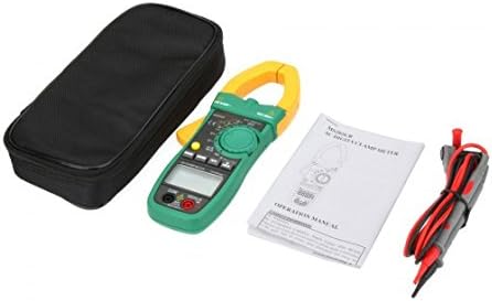
Figure 4.1: Contents of the MASTECH MS2026 package, including the clamp meter, test leads, user manual, and carrying case.
5. Setup
5.1. Battery Installation
- Ensure the meter is turned OFF.
- Locate the battery compartment cover on the back of the meter.
- Use a screwdriver to loosen the screw(s) securing the battery cover.
- Remove the battery cover.
- Insert three (3) 1.5V AA batteries, observing the correct polarity (+ and -) as indicated inside the compartment.
- Replace the battery cover and secure it with the screw(s).

Figure 5.1: Open battery compartment showing the placement for three 1.5V AA batteries.
5.2. Connecting Test Leads
For voltage, resistance, capacitance, diode, and continuity measurements, connect the test leads as follows:
- Insert the red test lead into the "VΩHz" input jack.
- Insert the black test lead into the "COM" input jack.

Figure 5.2: The MASTECH MS2026 clamp meter with red and black test leads properly connected to the input jacks.
6. Operating Instructions
The MASTECH MS2026 features a rotary switch for function selection and several buttons for additional features.

Figure 6.1: Detailed view of the MASTECH MS2026's rotary switch, function buttons, and LCD display.
6.1. Power On/Off
- Turn the rotary switch from "OFF" to any desired measurement function to power on the meter.
- Turn the rotary switch to "OFF" to power off the meter.
- The meter features an Auto Power Off function to conserve battery life.
6.2. AC Current Measurement (Clamp)
- Turn the rotary switch to the "A~" position. Select the appropriate range (6/60/600/1000A) if not in auto-range.
- Press the jaw release trigger to open the clamp.
- Encircle only one conductor of the circuit with the clamp jaws. Ensure the jaws are fully closed.
- Read the AC current value on the LCD display.
6.3. AC/DC Voltage Measurement
- Connect the test leads as described in Section 5.2.
- Turn the rotary switch to "V~" for AC voltage or "V--" for DC voltage.
- Touch the test probes to the desired test points in the circuit.
- Read the voltage value on the LCD display.
6.4. Resistance Measurement
- Connect the test leads as described in Section 5.2.
- Turn the rotary switch to the "Ω" position.
- Ensure the circuit under test is de-energized.
- Touch the test probes across the component or circuit where resistance is to be measured.
- Read the resistance value on the LCD display.
6.5. Capacitance Measurement
- Connect the test leads as described in Section 5.2.
- Turn the rotary switch to the "F" (Capacitance) position.
- Ensure the capacitor is fully discharged before testing.
- Touch the test probes across the capacitor terminals.
- Read the capacitance value on the LCD display.
6.6. Frequency Measurement
Frequency can be measured via the clamp or the test leads.
- Via Clamp: Turn the rotary switch to an AC current range (A~), then press the "Hz/%" button. Encircle a single conductor with the clamp.
- Via Test Leads: Connect the test leads as described in Section 5.2. Turn the rotary switch to the "Hz" position. Touch the test probes to the signal source.
Press the "Hz/%" button to toggle between frequency and duty cycle measurements.
6.7. Diode Check and Continuity Test
- Connect the test leads as described in Section 5.2.
- Turn the rotary switch to the "Diode/Continuity" position (often shared with Resistance).
- Press the "FUNC" button to toggle between Diode Check and Continuity Test.
- Diode Check: Touch the red probe to the anode and the black probe to the cathode of the diode. The display will show the forward voltage drop. Reverse the probes; the display should show "OL" (Open Loop) for a good diode.
- Continuity Test: Touch the test probes across the circuit or component. If continuity exists (resistance below a certain threshold), the meter will emit an audible beep.
6.8. Special Functions
- RANGE: Press this button to manually select the measurement range instead of auto-ranging. Press again to cycle through ranges or hold to return to auto-range.
- MAX/MIN: Press to record the maximum or minimum reading during a measurement session. Press again to toggle between MAX, MIN, and current reading.
- HOLD: Press to freeze the current reading on the display. Press again to release.
- Backlight/Work Light: The meter includes a backlight for the LCD and a work light for illuminating the measurement area.

Figure 6.2: The MASTECH MS2026 clamp meter's integrated work light illuminating a dark area, enhancing visibility during measurements.
7. Maintenance
7.1. Cleaning
Wipe the meter with a damp cloth and mild detergent. Do not use abrasives or solvents.
7.2. Battery Replacement
When the low battery indicator appears on the display, replace the batteries as described in Section 5.1. Remove batteries if the meter is not used for an extended period.
7.3. Fuse Replacement
This clamp meter typically does not have user-replaceable fuses for current measurement via the clamp. For other functions, if a fuse is present and needs replacement, it should be done by qualified personnel. Refer to the specifications for fuse type and rating if applicable.
8. Troubleshooting
| Problem | Possible Cause | Solution |
|---|---|---|
| Meter does not power on. | Dead or incorrectly installed batteries. | Check battery polarity and replace batteries if necessary (refer to Section 5.1). |
| "OL" (Overload) displayed. | Measurement exceeds the selected range or meter's maximum capacity. | Select a higher range or ensure the measurement is within the meter's specifications. |
| Inaccurate readings. | Low battery, incorrect function selected, or poor test lead connection. | Replace batteries, verify function selection, and ensure test leads are securely connected. |
| No continuity beep. | Circuit resistance is too high, or continuity function not selected. | Ensure continuity function is active (press FUNC button) and check the circuit for breaks. |
9. Specifications
| Measurement Type | Range | Accuracy |
|---|---|---|
| AC Voltage | 6V / 60V / 600V | ±1.2% |
| DC Voltage | 600mV / 6V / 60V / 600V | ±0.8% |
| AC Current | 6A / 60A / 600A / 1000A | ±2.0% |
| Resistance | 600Ω / 6kΩ / 60kΩ / 600kΩ / 6MΩ / 60MΩ | ±1.0% (600Ω to 6MΩ), ±5.0% (60MΩ) |
| Capacitance | 40nF / 400nF / 4µF / 40µF / 400µF / 4000µF | ±4.0% |
| Frequency (Clamp) | 0 ~ 1 kHz | ±1.5% |
| Frequency (Plug) | 0 ~ 10 MHz | ±0.5% |
General Specifications
- Display: 6000 Counts LCD
- Jaw Opening: Up to 40mm (1.6 inches)
- Power Supply: 3 x 1.5V AA Batteries
- Dimensions: 225mm x 86mm x 33mm
- Product Weight: Approximately 320g (0.7 lb)
- Overload Protection: Yes, on all ranges
- Auto Power Off: Yes
- Low Battery Indication: Yes
- Safety Rating: CAT III 600V
10. Warranty and Support
Information regarding product warranty and customer support was not available in the provided product data. Please refer to the product packaging or contact your point of purchase for details on warranty coverage and technical assistance.


