
1. Introduction
This manual provides essential instructions for the safe and effective operation of your Mastech MY61 Digital Multimeter. The MY61 is a portable, battery-powered digital multimeter designed for measuring DC and AC voltage, DC and AC current, resistance, capacitance, diode, and transistor (hFE) parameters. It features a 2000-count display, data hold function, and auto power-off for energy conservation. Please read this manual thoroughly before use to ensure proper operation and to prevent potential hazards.

Image 1.1: Front view of the Mastech MY61 Digital Multimeter, showing the display, rotary switch, and input jacks.
2. Safety Information
To ensure safe operation and service of the meter, follow these instructions. Failure to observe these warnings can result in severe injury or death.
- Always read the manual: Before using the multimeter, carefully read and understand all safety warnings and operating instructions.
- Electrical Shock Hazard: Be extremely cautious when working with voltages above 30V AC RMS, 42V peak, or 60V DC. These voltages pose a shock hazard.
- Inspect Test Leads: Before each use, inspect the test leads for damaged insulation or exposed metal. Replace damaged leads immediately.
- Do Not Operate if Damaged: Do not use the meter if it appears damaged or if the case is open.
- Correct Input Terminals: Always connect the test leads to the correct input terminals for the measurement function selected.
- Select Correct Function and Range: Ensure the rotary switch is set to the appropriate function and range before making any measurement.
- Overload Protection: The meter is equipped with full function overload protection. However, avoid exceeding the maximum input values specified in the specifications section.
- Battery Replacement: To avoid electrical shock, remove all inputs before opening the battery compartment or case. Replace the battery when the low battery indicator appears.
- Working Environment: Do not operate the meter in explosive gas, vapor, or dust environments.

Image 2.1: Back view of the Mastech MY61 Digital Multimeter, showing the kickstand and a warning label regarding electrical shock and the need to read the manual for safety.
3. Package Contents
Upon opening the package, please verify that all items listed below are present and undamaged:
- 1 x Mastech MY61 Digital Multimeter
- 1 x Pair of Test Leads (Red and Black)
- 1 x English Instruction Manual

Image 3.1: Contents of the Mastech MY61 package, including the multimeter, test leads, and instruction manual.
4. Product Overview
The Mastech MY61 Digital Multimeter features a robust design with clear markings for ease of use. Key components include:
- LCD Display: 2000-count digital display for clear readings.
- Rotary Switch: Used to select measurement functions and ranges.
- Function Buttons: Includes 'HOLD' for data retention and 'ON/OFF' for power control.
- Input Jacks:
- COM Jack: Common terminal for all measurements (black test lead).
- VΩmA Jack: Input for voltage, resistance, capacitance, diode, hFE, and current measurements up to 200mA (red test lead).
- 20A Jack: Input for high current measurements up to 20A (red test lead).
- hFE Socket: For transistor testing.
- Kickstand: Integrated stand on the back for convenient viewing angle.

Image 4.1: Angled front view of the Mastech MY61, highlighting the display and control layout.

Image 4.2: Close-up of the Mastech MY61's rotary switch, function buttons, and LCD display.

Image 4.3: Side view of the Mastech MY61 with its integrated kickstand extended for desktop use.
5. Setup
5.1 Battery Installation
The Mastech MY61 requires one 9V (6F22) battery for operation. The battery is not included in the package.
- Ensure the multimeter is powered off and disconnect all test leads from the input jacks.
- Locate the battery compartment cover on the back of the meter.
- Use a screwdriver to loosen the screw securing the battery cover, then remove the cover.
- Connect a new 9V battery to the battery clip, observing correct polarity.
- Place the battery into the compartment and replace the cover, securing it with the screw.
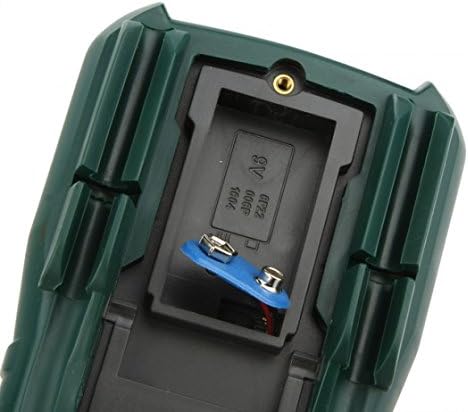
Image 5.1: View of the battery compartment on the Mastech MY61, showing where the 9V battery is installed.
5.2 Connecting Test Leads
Always connect the black test lead to the COM (Common) jack. The red test lead connection depends on the measurement function:
- For Voltage, Resistance, Capacitance, Diode, hFE, and current up to 200mA, connect the red test lead to the VΩmA jack.
- For current measurements between 200mA and 20A, connect the red test lead to the 20A jack.

Image 5.2: Test leads properly connected to the Mastech MY61 Digital Multimeter's input jacks.
6. Operating Instructions
6.1 Power ON/OFF and Data Hold
- Power ON: Press the red 'ON/OFF' button to turn the meter on.
- Power OFF: Press the red 'ON/OFF' button again to turn the meter off. The meter also features an auto power-off function to conserve battery life.
- Data Hold: Press the yellow 'HOLD' button to freeze the current reading on the display. Press it again to release the hold function.
6.2 DC Voltage Measurement
- Connect the black test lead to the COM jack and the red test lead to the VΩmA jack.
- Set the rotary switch to the desired DC Voltage range (V—). If the voltage is unknown, start with the highest range (1000V) and decrease as needed.
- Connect the test probes in parallel to the circuit or component under test.
- Read the voltage value on the LCD display.
6.3 AC Voltage Measurement
- Connect the black test lead to the COM jack and the red test lead to the VΩmA jack.
- Set the rotary switch to the desired AC Voltage range (V∼). If the voltage is unknown, start with the highest range (750V) and decrease as needed.
- Connect the test probes in parallel to the circuit or component under test.
- Read the voltage value on the LCD display.
6.4 DC Current Measurement
- Important: Current measurements require the meter to be connected in series with the circuit. Ensure the circuit is de-energized before connecting the meter.
- Connect the black test lead to the COM jack. For currents up to 200mA, connect the red test lead to the VΩmA jack. For currents up to 20A, connect the red test lead to the 20A jack.
- Set the rotary switch to the desired DC Current range (A— or mA—). Start with the highest range if the current is unknown.
- Open the circuit where the current is to be measured and connect the test probes in series.
- Apply power to the circuit and read the current value on the LCD display.
6.5 AC Current Measurement
- Important: Current measurements require the meter to be connected in series with the circuit. Ensure the circuit is de-energized before connecting the meter.
- Connect the black test lead to the COM jack. For currents up to 200mA, connect the red test lead to the VΩmA jack. For currents up to 20A, connect the red test lead to the 20A jack.
- Set the rotary switch to the desired AC Current range (A∼ or mA∼). Start with the highest range if the current is unknown.
- Open the circuit where the current is to be measured and connect the test probes in series.
- Apply power to the circuit and read the current value on the LCD display.
6.6 Resistance Measurement
- Ensure the circuit or component is de-energized before measuring resistance.
- Connect the black test lead to the COM jack and the red test lead to the VΩmA jack.
- Set the rotary switch to the desired Resistance range (Ω). Start with a higher range if the resistance is unknown.
- Connect the test probes across the component to be measured.
- Read the resistance value on the LCD display.
6.7 Capacitance Measurement
- Ensure the capacitor is fully discharged before measurement to prevent damage to the meter.
- Connect the black test lead to the COM jack and the red test lead to the VΩmA jack.
- Set the rotary switch to the desired Capacitance range (F).
- Connect the test probes across the capacitor.
- Read the capacitance value on the LCD display.
6.8 Diode Test
- Ensure the diode is disconnected from the circuit.
- Connect the black test lead to the COM jack and the red test lead to the VΩmA jack.
- Set the rotary switch to the Diode Test position (→|).
- Connect the red probe to the anode and the black probe to the cathode of the diode. The display will show the forward voltage drop.
- Reverse the probes. The display should show 'OL' (Open Loop) for a good diode.
6.9 Transistor (hFE) Test
- Set the rotary switch to the hFE position.
- Identify if the transistor is NPN or PNP.
- Insert the transistor leads (Emitter, Base, Collector) into the corresponding holes in the hFE socket on the meter, ensuring correct type (NPN/PNP) and pinout.
- Read the hFE value (DC current gain) on the LCD display.
6.10 Continuity Test
- Ensure the circuit or component is de-energized.
- Connect the black test lead to the COM jack and the red test lead to the VΩmA jack.
- Set the rotary switch to the Continuity Test position (♫).
- Connect the test probes across the component or circuit path.
- If continuity exists (resistance below approximately 50Ω), the built-in buzzer will sound. The display will show the resistance value.
7. Maintenance
7.1 Cleaning
Wipe the meter with a damp cloth and mild detergent. Do not use abrasives or solvents. Ensure the meter is completely dry before use.
7.2 Battery Replacement
When the low battery indicator appears on the display, replace the 9V battery as described in Section 5.1. Always use a fresh 9V (6F22) battery.
7.3 Fuse Replacement
The MY61 multimeter is equipped with internal fuses to protect against overcurrent. If the current measurement function fails, the fuse may need replacement. Fuse replacement should only be performed by qualified personnel. Refer to the specifications for fuse ratings. To access the fuse, the entire back case of the meter must be opened, which requires removing the battery compartment cover and additional screws. Always disconnect test leads and power before opening the case.
8. Troubleshooting
If your Mastech MY61 Digital Multimeter is not functioning as expected, refer to the following common issues and solutions:
- No Display or Faint Display:
- Check if the meter is powered on.
- Replace the 9V battery if it is low or depleted.
- Incorrect Readings:
- Ensure the rotary switch is set to the correct function and range for the measurement.
- Verify that the test leads are connected to the correct input jacks.
- Check for proper contact between the test probes and the circuit/component.
- Ensure the circuit or component is de-energized for resistance and capacitance measurements.
- Current Measurement Not Working:
- Check if the test leads are connected to the correct current input jack (VΩmA for mA, 20A for A).
- The internal fuse for current measurement may be blown. Refer to Section 7.3 for fuse replacement information.
- 'OL' (Overload) Displayed:
- The measured value exceeds the selected range. Switch to a higher range.
- For resistance, 'OL' can indicate an open circuit.
9. Specifications
| Function | Range | Accuracy |
|---|---|---|
| DC Voltage | 200mV, 2V, 20V, 200V | ±(0.5%+2) |
| 1000V | ±(0.8%+2) | |
| AC Voltage | 200mV | ±(1.2%+3) |
| 2V, 20V, 200V | ±(0.8%+3) | |
| 750V | ±(1.2%+3) | |
| DC Current | 2mA, 20mA, 200mA | ±(1.2%+3) |
| 20A | ±(2.0%+5) | |
| AC Current | 2mA, 20mA, 200mA | ±(1.8%+5) |
| 20A | ±(3.0%+5) | |
| Resistance | 200Ω, 2kΩ, 20kΩ, 200kΩ, 2MΩ | ±(0.8%+3) |
| 20MΩ | ±(1.0%+2) | |
| 200MΩ | ±(6.0%+10) | |
| Capacitance | 20nF, 200nF, 2µF, 20µF | ±(4.0%+3) |
| 200µF | ±(6.0%+10) |
General Characteristics:
- Display: 2000 Counts LCD
- Data Hold: Yes
- Auto Power Off: Yes
- Diode Test: Yes
- Transistor (hFE) Test: Yes
- Continuity Test: Yes
- Overload Protection: Full function
- Power: 1 x 9V (6F22) Battery (not included)
- Color: Dark green
- Operating Temperature: 0°C to 40°C (32°F to 104°F)
- Storage Temperature: -10°C to 50°C (14°F to 122°F)
- Dimensions: Approximately 140mm x 70mm x 35mm (5.5in x 2.7in x 1.4in)
- Weight: Approximately 200g (7.05 oz) without battery
10. Warranty and Support
For warranty information and technical support, please refer to the warranty card included with your product or contact Mastech customer service through their official website. Keep your purchase receipt as proof of purchase for any warranty claims.


