
Sick I110-RP313
Contents
User Manual
Sick I110-RP313 Safety Switch
Model: I110-RP313
1. Introduction
This manual provides essential information for the safe and effective installation, operation, and maintenance of the Sick I110-RP313 Safety Switch. Please read this manual thoroughly before attempting any installation or operation to ensure proper functionality and safety.
The Sick I110-RP313 is a robust safety switch designed for industrial applications, ensuring machine and personnel safety by monitoring the position of guards or other movable machine parts. Its durable construction and reliable operation make it suitable for demanding environments.
2. Safety Information
WARNING: Failure to follow these safety instructions may result in serious injury or death.
- Installation and maintenance must only be performed by qualified personnel familiar with industrial safety standards and electrical systems.
- Always disconnect power to the machine before installing, servicing, or removing the safety switch.
- Ensure all wiring conforms to local and national electrical codes.
- Do not bypass or tamper with the safety switch. Any modification will void the warranty and compromise safety.
- Regularly inspect the switch for damage or wear. Replace immediately if any damage is found.
- This device is part of a safety system. Its proper function depends on the correct integration into the overall safety circuit.
3. Setup and Installation
The Sick I110-RP313 Safety Switch is designed for panel mounting. Follow these steps for proper installation:
- Mounting Location: Select a mounting location that ensures the switch is protected from excessive mechanical stress, vibration, and extreme temperatures. Ensure the actuator can engage and disengage smoothly.
- Physical Mounting: Securely mount the switch to a stable surface using appropriate fasteners. The mounting type is Panel Mount.
- Wiring:
- Refer to the wiring diagram provided with your specific product variant for correct electrical connections.
- Ensure power is disconnected before wiring.
- Connect the safety switch into the machine's safety circuit according to the required safety category. The operation mode is ON-OFF.
- Ensure proper grounding.
- Actuator Alignment: Carefully align the actuator with the switch head to ensure proper engagement and disengagement. The switch should activate reliably when the guard is closed and deactivate when it is opened.
- Testing: After installation, perform a thorough functional test of the safety circuit to verify correct operation of the switch and the entire safety system.

Figure 3.1: Main view of the Sick I110-RP313 Safety Switch. This image shows the overall form factor of the device, including its yellow housing and connection points.
4. Operating Instructions
The Sick I110-RP313 Safety Switch operates as a position monitoring device within a safety circuit. Its primary function is to detect the state of a machine guard or door.
- Normal Operation: When the machine guard is closed, the actuator engages with the safety switch, allowing the machine to operate.
- Safety Function: If the machine guard is opened, the actuator disengages from the switch, causing the safety contacts to open. This action immediately stops the machine or prevents its startup, ensuring personnel safety.
- Monitoring: The switch provides feedback to the safety control system, indicating the status of the guard.
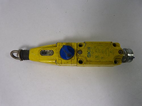
Figure 4.1: Top view of the Sick I110-RP313 Safety Switch. This perspective highlights the blue button and the overall elongated shape of the switch.
5. Maintenance
Regular maintenance ensures the longevity and reliable operation of your Sick I110-RP313 Safety Switch.
- Visual Inspection: Periodically inspect the switch and its actuator for any signs of physical damage, wear, corrosion, or loose connections. Check for excessive dirt or debris accumulation.
- Cleaning: Clean the exterior of the switch with a soft, damp cloth. Do not use abrasive cleaners or solvents. Ensure the switch is dry before re-energizing.
- Functional Test: Regularly test the safety function of the switch by opening and closing the guard to ensure the machine stops or does not start as intended.
- Actuator Check: Verify that the actuator engages and disengages smoothly without binding or excessive play.
- Replacement: If any damage, excessive wear, or malfunction is detected, replace the safety switch immediately with an original Sick I110-RP313 or an approved equivalent.
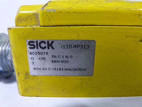
Figure 5.1: Close-up view of the product label on the Sick I110-RP313 Safety Switch. This image shows the model number "i110-RP313" and other identifying information.
6. Troubleshooting
This section provides guidance for common issues you might encounter with the Sick I110-RP313 Safety Switch.
| Problem | Possible Cause | Solution |
|---|---|---|
| Machine does not start when guard is closed. |
|
|
| Machine stops unexpectedly. |
|
|
| Switch appears physically damaged. |
|
|
If the problem persists after attempting these solutions, contact qualified technical support.
7. Specifications
| Attribute | Value |
|---|---|
| Model | I110-RP313 |
| Brand | Sick |
| Product Dimensions (L x W x H) | 12.2 x 9.06 x 9.06 inches |
| Weight | 4.41 Pounds |
| Operation Mode | ON-OFF |
| Mounting Type | Panel Mount |
| International Protection Rating | IP54 |
| Connectivity Protocol | Wi-Fi (Note: This specification may refer to a specific variant or communication module. Verify with product datasheet if connectivity is critical.) |
| Number of Items | 1 |
8. Warranty and Support
For specific warranty information and technical support, please refer to the official Sick website or contact your authorized Sick distributor. Keep your purchase receipt for warranty claims.
Sick Official Website: www.sick.com
Customer Service: Refer to the contact information provided on the official Sick website for your region.
Ask a question about this manual
Ask about setup, troubleshooting, compatibility, parts, safety, or missing instructions. Manuals+ will review the question and use this page’s manual context to help answer it.