1. Introduction
This manual provides essential information for the safe and efficient operation of your COTEC SP2000-224 Pure Sine Wave Inverter. This advanced inverter offers high efficiency and power density, featuring selectable output voltage and frequency, all housed within a robust aluminum casing. Please read this manual thoroughly before installation and use to ensure proper function and longevity of the device.
2. Safety Information
Always observe the following safety precautions to prevent injury and damage to the inverter or connected equipment:
- Ventilation: Ensure adequate ventilation around the inverter. Do not block ventilation openings.
- Environment: Install the inverter in a dry, cool, and well-ventilated area, away from direct sunlight, heat sources, and flammable materials.
- Grounding: Properly ground the inverter chassis to prevent electrical shock.
- DC Input: Connect the inverter only to a 24V DC battery bank. Ensure correct polarity (positive to positive, negative to negative). Reverse polarity will damage the unit.
- AC Output: Do not overload the inverter. Ensure the total wattage of connected AC devices does not exceed the inverter's rated output.
- Servicing: Do not attempt to open or service the inverter yourself. Refer all servicing to qualified personnel.
- Water Exposure: Keep the inverter away from water, rain, or excessive moisture.
3. Product Features
The COTEC SP2000-224 Inverter incorporates several advanced features for reliable power conversion:
- Pure sine wave output for sensitive electronics.
- Power ON / OFF remote control capability via a dedicated green terminal.
- Full input and output isolation for enhanced safety.
- Temperature and load-controlled cooling fan for efficient heat dissipation.
- User-friendly interface with 3-color LED status indicators.
- Output frequency selectable between 50 Hz and 60 Hz via DIP switch.
- Output voltage selectable via DIP switch.
- Power saving mode adjustable via a variable resistor.
- Comprehensive input protection: Reverse Polarity (via fuse), Under Voltage, Over Voltage.
- Comprehensive output protection: Short Circuit, Overload, Over Temperature.
- Certifications: E13, UL, CE, FCC approved.
4. Setup and Installation
Proper installation is crucial for the inverter's performance and safety.
4.1 Physical Installation
Mount the inverter securely in a location that meets the safety requirements mentioned in Section 2. Ensure sufficient space around the unit for airflow.
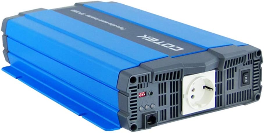
Figure 4.1: Angled view of the COTEC SP2000-224 Pure Sine Wave Inverter, showcasing its robust blue and gray casing.
4.2 DC Input Connection
Connect the inverter to a 24V DC battery bank using appropriate gauge cables. Ensure the positive (+) terminal of the inverter connects to the positive terminal of the battery, and the negative (-) terminal of the inverter connects to the negative terminal of the battery. Install an appropriate fuse or circuit breaker in the positive DC line close to the battery.

Figure 4.2: Rear view of the inverter, highlighting the DC input terminals (red for positive, black for negative), the chassis ground screw, and the remote control terminal.
4.3 Chassis Ground Connection
Connect the chassis ground terminal (labeled 'CHASSIS GROUND') to a reliable earth ground point. This is a critical safety step.
4.4 AC Output and Controls
The inverter features a standard AC outlet and control switches on its front panel.

Figure 4.3: Front view of the inverter, displaying the AC output socket, the main power switch, LED indicators, and DIP switches for configuration.
4.5 DIP Switch Settings
The inverter features DIP switches for configuring output frequency and voltage. Refer to the specifications table (Section 7) or the product label for specific settings. Ensure the inverter is powered off before adjusting DIP switches.
- Output Frequency: Select 50 Hz or 60 Hz based on your regional requirements.
- Output Voltage: Select the desired AC output voltage (e.g., 230VAC for this model).
5. Operating Instructions
5.1 Powering On/Off
After all connections are secure and verified, switch the main power button on the inverter to the 'ON' position. The LED indicators will illuminate to show the inverter's status. To power off, switch the button to 'OFF'. A remote control terminal is also available for external ON/OFF control.
5.2 LED Indicators
The 3-color LED indicators provide visual feedback on the inverter's operational status and any potential faults. Consult the product documentation or the specifications table for a detailed explanation of each LED state.
5.3 Power Saving Mode
The power saving mode can be adjusted via a variable resistor. This feature helps reduce quiescent current draw when no load or a very light load is connected, conserving battery power.
5.4 Connecting AC Loads
Plug your AC appliances into the inverter's AC output socket. Ensure the total power consumption does not exceed the inverter's continuous power rating (2000W for this model). For inductive loads (e.g., motors, refrigerators), consider their surge power requirements, which can be significantly higher than their running power.
6. Maintenance
Regular maintenance ensures optimal performance and extends the lifespan of your inverter.
- Cleaning: Keep the inverter clean and free from dust. Use a dry cloth to wipe the exterior. Do not use liquid cleaners.
- Ventilation: Periodically check that the cooling fan and ventilation openings are clear of obstructions.
- Connections: Inspect all DC and AC connections regularly to ensure they are tight and free from corrosion. Loose connections can cause overheating and poor performance.
- Battery Maintenance: Follow the manufacturer's recommendations for your battery bank's maintenance.
7. Troubleshooting
If the inverter is not functioning correctly, refer to the following common issues and solutions:
- No Output Power:
- Check DC input connections and battery voltage.
- Verify the inverter's power switch is ON.
- Check for blown DC input fuses (if applicable).
- Overload Indication:
- Reduce the total load connected to the inverter.
- Disconnect and reconnect the load to reset the inverter.
- Over Temperature Indication:
- Ensure adequate ventilation around the inverter.
- Check if the cooling fan is operating.
- Reduce the load if operating in a hot environment.
- Low Battery Voltage Alarm/Shutdown:
- Recharge the battery bank.
- Check battery connections for looseness or corrosion.
For persistent issues, contact COTEC customer support.
8. Specifications
The following table details the technical specifications for the COTEC SP2000 series, with specific values for the SP2000-224 model highlighted where applicable.

Figure 8.1: Detailed technical specifications for the COTEC SP-2000 series, including the SP2000-224 model.
| Feature | Specification |
|---|---|
| Brand | COTEK |
| Model Name | SP2000 (SP2000-224 variant) |
| Rated Power | 2000W |
| Surge Power (1 Sec) | 4000W |
| DC Input Voltage | 24VDC (Operating Range: 21.0-33.0VDC) |
| AC Output Voltage | 230VAC (selectable) |
| Output Frequency | 50/60 Hz (selectable) |
| Output Waveform | Pure Sine Wave (THD<3% at nominal load) |
| Efficiency (Max) | 93% |
| Cooling | Temperature & load controlled fan |
| Operating Temperature | -20°C to +40°C |
| Storage Temperature | -30°C to +70°C |
| Dimensions (W x H x D) | 17.44 x 9.76 x 3.27 inches (443 x 248 x 83 mm) |
| Item Weight | 1 pounds (approximate, actual unit weight may vary) |
| Package Dimensions | 19 x 12 x 6 inches |
| Certifications | E13, UL, CE, FCC approved |
8.1 Mechanical Drawings
For detailed physical dimensions and mounting information, refer to the mechanical drawings below.
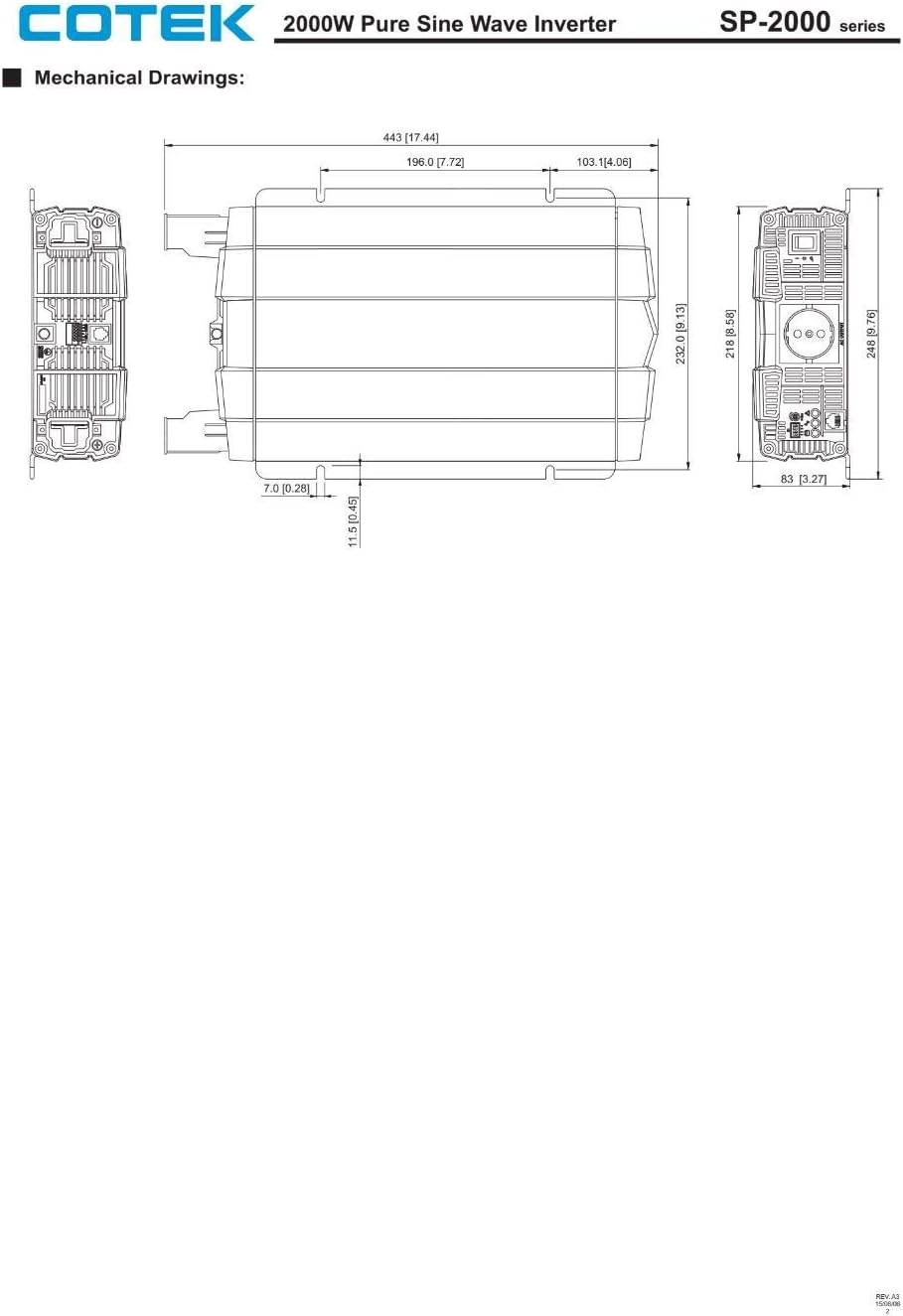
Figure 8.2: Mechanical drawings providing precise dimensions for installation planning.
9. Warranty and Support
COTEC products are designed for reliability and performance. For warranty information, technical support, or service inquiries, please refer to the warranty card included with your product or visit the official COTEC website. Keep your purchase receipt as proof of purchase for warranty claims.


