1. Introduction
This manual provides detailed instructions for the installation, operation, and maintenance of the Cotek SP-1000-224 Pure Sine Wave Inverter. This inverter is designed to convert 24VDC power to 230VAC, providing a stable and reliable power source for various applications.
Key Features:
- Pure sine wave output for sensitive electronics.
- Power ON / OFF remote control capability (Green Terminal).
- Input & output fully isolated for enhanced safety.
- Temperature & load controlled cooling fan for optimal performance.
- User-friendly interface.
- Output frequency (50/60 Hz) selectable via DIP switch.
- Output voltage selectable via DIP switch.
- Power saving mode adjustable via variable resistor.
- 3-color LED status indicators for easy monitoring.
- Comprehensive input protection: Reverse Polarity (Fuse), Under Voltage, Over Voltage.
- Robust output protection: Short Circuit, Overload, Over Temperature.
- Type 1 Indoor Aluminum Enclosure.
- E13 / UL / CE / FCC approved.
2. Safety Information
WARNING: Please read and understand all safety instructions before installing or operating this inverter. Failure to follow these instructions may result in electric shock, fire, serious injury, or death.
- Electrical Hazard: This unit produces high voltage. Do not open the inverter casing. Refer all servicing to qualified personnel.
- Battery Safety: Work in a well-ventilated area. Batteries can produce explosive gases. Do not smoke or allow sparks or flames near the battery.
- Proper Ventilation: Ensure adequate airflow around the inverter. Do not block ventilation openings.
- Environmental Conditions: Do not expose the inverter to rain, moisture, or excessive dust. Operate in a dry, cool environment.
- Grounding: The inverter must be properly grounded. Follow all local and national electrical codes.
- Load Capacity: Do not exceed the inverter's rated power output. Overloading can cause damage to the inverter and connected devices.
- California Proposition 65 Warning: This product may contain materials cautioned by California Proposition 65.
3. Product Overview and Components
Familiarize yourself with the various parts of your Cotek SP-1000-224 Pure Sine Wave Inverter.

Figure 3.1: Angled view of the Cotek SP-1000-224 Pure Sine Wave Inverter, showing its blue aluminum casing and grey end caps with ventilation and connection ports.

Figure 3.2: Front panel of the inverter, featuring the AC output socket (Schuko type), a power switch, LED indicators, and DIP switches for configuration.

Figure 3.3: Rear panel of the inverter, showing the DC input terminals for battery connection, a remote control port (RJ45), and a green terminal block for remote ON/OFF control.

Figure 3.4: Side view of the inverter, highlighting its robust blue aluminum heat sink casing designed for efficient heat dissipation.
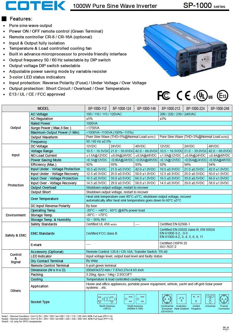
Figure 3.5: A detailed table outlining the features and technical specifications of the Cotek SP-1000 series inverters, including input/output parameters, protections, and certifications.

Figure 3.6: Mechanical drawings providing dimensions of the inverter, along with power voltage and power temperature curves illustrating performance characteristics.
4. Setup and Installation
4.1 Choosing a Location:
- Install the inverter in a dry, cool, and well-ventilated area.
- Avoid direct sunlight, heat sources, and moisture.
- Ensure sufficient clearance around the inverter for proper airflow, especially around the cooling fan and ventilation openings.
- Mount the inverter securely on a stable, non-combustible surface.
4.2 DC Input Connection:
- Ensure the inverter's power switch is in the OFF position.
- Connect the positive (+) terminal of the 24VDC battery bank to the positive (+) DC input terminal on the inverter.
- Connect the negative (-) terminal of the 24VDC battery bank to the negative (-) DC input terminal on the inverter.
- Use appropriately sized cables to minimize voltage drop and ensure safe operation. Refer to electrical standards for cable sizing.
- Ensure all connections are tight and secure.
4.3 AC Output Connection:
- Plug your AC appliances directly into the AC output socket on the inverter.
- Ensure the total power consumption of all connected appliances does not exceed the inverter's 1000W continuous output rating.
4.4 Grounding:
Proper grounding is essential for safety. Connect the inverter's chassis ground terminal to a reliable earth ground using a suitable grounding wire. Consult local electrical codes for specific grounding requirements.
4.5 Remote Control (Optional):
The inverter supports remote ON/OFF control via the green terminal block or an optional RJ45 remote control unit. Refer to the accessory manual for detailed instructions on connecting and using the remote control.
4.6 DIP Switch Configuration:
The inverter features DIP switches on the front panel to select output frequency (50/60 Hz) and output voltage. Refer to the table below for common settings. Ensure the inverter is OFF before changing DIP switch settings.
| Setting | DIP Switch Position |
|---|---|
| Output Frequency 50Hz | Switch 1: OFF, Switch 2: OFF (Example, refer to actual product manual/Figure 3.5) |
| Output Frequency 60Hz | Switch 1: ON, Switch 2: OFF (Example, refer to actual product manual/Figure 3.5) |
| Output Voltage 230VAC | Switch 3: ON, Switch 4: OFF (Example, refer to actual product manual/Figure 3.5) |
Note: The exact DIP switch configurations for specific voltage and frequency settings are detailed in the product's full technical specifications (refer to Figure 3.5). Always verify settings before operation.
5. Operation
5.1 Powering On the Inverter:
- Ensure all DC and AC connections are secure and correct.
- If using the remote control, ensure it is connected and in the ON position.
- Flip the main power switch on the inverter's front panel to the "ON" position.
- Observe the 3-color LED status indicators. A green light indicates normal operation.
5.2 LED Status Indicators:
- Green: Normal operation.
- Yellow/Amber: Warning (e.g., input voltage slightly low/high, minor overload). The inverter may continue to operate but requires attention.
- Red: Fault condition (e.g., severe overload, short circuit, over-temperature, critical input voltage). The inverter will shut down to protect itself and connected devices.
5.3 Power Saving Mode:
The inverter features a power saving mode, adjustable via a variable resistor. This mode reduces power consumption when no load or a very light load is detected. Adjust the resistor to set the sensitivity for entering/exiting power saving mode.
5.4 Powering Off the Inverter:
- Turn off all connected AC appliances.
- Flip the main power switch on the inverter's front panel to the "OFF" position.
- If using a remote control, turn it off as well.
6. Maintenance
Regular maintenance ensures the longevity and reliable operation of your inverter.
- Cleaning: Periodically clean the exterior of the inverter with a dry, soft cloth. Do not use liquid cleaners or solvents. Ensure ventilation openings are free from dust and debris.
- Connections: Periodically check all DC and AC connections to ensure they are tight and free from corrosion. Loose connections can cause overheating and poor performance.
- Ventilation: Ensure the cooling fan and ventilation grilles are not obstructed. The fan operates based on temperature and load, so ensure it can draw and expel air freely.
- Battery Health: Monitor the health of your battery bank. A weak or failing battery can negatively impact inverter performance and lifespan.
WARNING: Do not attempt to service the inverter yourself. There are no user-serviceable parts inside. Refer all servicing to qualified personnel.
7. Troubleshooting
This section provides solutions to common issues you might encounter with your inverter. If the problem persists after following these steps, contact customer support.
| Problem | Possible Cause | Solution |
|---|---|---|
| Inverter does not turn on (No LED indication) |
|
|
| Red LED is on, inverter shuts down |
|
|
| Yellow/Amber LED is on |
|
|
| No AC output |
|
|
8. Technical Specifications
The following table provides detailed technical specifications for the Cotek SP-1000-224 Pure Sine Wave Inverter. For a comprehensive overview, refer to Figure 3.5.
| Parameter | Value (SP-1000-224) |
|---|---|
| Model | SP-1000-224 |
| AC Output Voltage | 230VAC (selectable) |
| DC Input Voltage | 24VDC |
| Continuous Power | 1000W |
| Surge Power (3 sec) | 1750VA |
| Output Waveform | Pure Sine Wave (THD < 3%) |
| Output Frequency | 50/60 Hz (selectable) |
| Efficiency (Max) | 92% |
| Input Under Voltage Protection | 21.0 ± 0.5VDC |
| Input Over Voltage Protection | 33.0 ± 0.5VDC |
| Operating Temperature | -20°C ~ +40°C (60% power load) |
| Dimensions (L x W x H) | 17 x 10 x 6 inches (approx.) |
| Weight | 8.94 pounds |
| Certifications | E13 / UL / CE / FCC approved |
Note: Specifications are subject to change without notice. Always refer to the product label or manufacturer's official documentation for the most accurate and up-to-date information.
9. Warranty Information
COTEK products are manufactured to high quality standards. For specific warranty terms and conditions, including duration and coverage, please refer to the warranty card included with your product or visit the official COTEK website. Keep your proof of purchase for warranty claims.
Typical warranties cover defects in materials and workmanship under normal use. Damage caused by improper installation, misuse, abuse, or unauthorized modifications is generally not covered.
10. Customer Support
If you have any questions, require technical assistance, or need to report an issue with your Cotek SP-1000-224 Pure Sine Wave Inverter, please contact COTEK customer support or your authorized dealer.
When contacting support, please have the following information ready:
- Product Model: SP-1000-224
- Serial Number (if applicable, usually found on the product label)
- Date of Purchase
- A detailed description of the issue you are experiencing.
For the most up-to-date contact information, please visit the official COTEK website: www.cotek.com.tw (This is a placeholder URL, please verify the actual manufacturer website).


