
1. Introduction
The TekPower TP12001X is a professional DC regulated switching power supply designed for various applications requiring a stable and adjustable DC voltage and current. This unit provides a continuously adjustable output from 0-120V DC at 1A. Key features include a low ripple and noise design, a large LCD display with backlight for accurate voltage and current readings, and an automatic cooling fan for extended operation.
This manual provides essential information for the safe and efficient operation, setup, and maintenance of your TP12001X power supply. Please read it thoroughly before use.
2. Safety Instructions
To prevent electric shock, injury, or damage to the unit, observe the following safety precautions:
- Always connect the power supply to a grounded AC outlet.
- Do not operate the unit in wet or damp conditions.
- Ensure proper ventilation; do not block the cooling fan or vents.
- Do not open the casing; there are no user-serviceable parts inside. Refer servicing to qualified personnel.
- Verify the input voltage matches your local power supply (110V for this model).
- Before making any connections or disconnections, ensure the power supply is turned off.
- Avoid short-circuiting the output terminals.
- Use appropriate cables and connectors rated for the voltage and current.
3. Product Overview
3.1 Front Panel

Figure 3.1: Front Panel of the TP12001X Power Supply.
The front panel features the digital display for voltage and current, power switch, current and voltage adjustment controls, and output terminals. The display shows the output voltage in Volts (V) and output current in Amperes (A). The "CUR-ADJ" buttons (UP/DOWN) adjust the current limit, and the "VOL-ADJ" knob adjusts the output voltage. The "CC/CV" indicator shows whether the unit is operating in Constant Current or Constant Voltage mode. Output terminals include a negative (black), ground (green), and positive (red) banana jack connections, as well as an external screw terminal block for higher current or more permanent connections.
3.2 Rear Panel
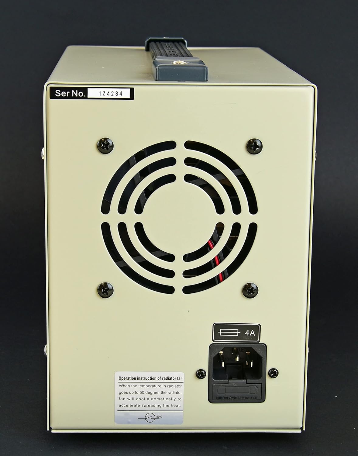
Figure 3.2: Rear Panel of the TP12001X Power Supply.
The rear panel includes the AC power input socket, the main fuse holder, and the cooling fan. The fan automatically activates when the internal temperature reaches approximately 50°C to ensure optimal operating conditions and prevent overheating. Ensure adequate clearance around the fan for proper airflow.
4. Setup
- Unpacking: Carefully remove the power supply from its packaging. Inspect the unit for any signs of damage during transit.
- Placement: Place the power supply on a stable, level surface. Ensure there is sufficient space around the unit (at least 10 cm or 4 inches) for proper ventilation, especially around the rear cooling fan and side vents.
- Power Connection:
- Ensure the power switch on the front panel is in the "OFF" position.
- Connect the provided AC power cord to the power input socket on the rear panel.
- Plug the other end of the AC power cord into a grounded 110V AC outlet.
- Output Connections:
- Before connecting any load, ensure the power supply is off and the output voltage knob is set to minimum (fully counter-clockwise).
- Connect your load to the output terminals. You can use the banana jacks (red for positive, black for negative, green for ground) or the external screw terminal block. Ensure correct polarity.
- For the external screw terminal block, loosen the screws, insert the wire, and tighten securely.

Figure 4.1: Connecting test leads to the front panel output terminals.
The power supply comes with test leads, typically with banana plugs on one end and alligator clips on the other, for convenient connection to your circuit or device. Ensure these leads are properly inserted into the corresponding positive (+) and negative (-) terminals.
5. Operating Instructions
5.1 Powering On and Initial Adjustment
- Ensure all connections are secure and correct.
- Turn on the power supply using the "ON/OFF" switch on the front panel. The digital display will illuminate.
- Setting Voltage: Rotate the "VOL-ADJ" knob clockwise to increase the output voltage and counter-clockwise to decrease it. Observe the voltage reading on the display.
- Setting Current Limit (Constant Current Mode):
- To set the current limit, it is recommended to short-circuit the output terminals temporarily (e.g., by connecting a wire between the positive and negative terminals). The "CC" indicator should light up, indicating Constant Current mode.
- Use the "CUR-ADJ" UP/DOWN buttons to set the desired maximum current. The current display will show the set limit.
- Remove the short circuit. The power supply will now operate in Constant Voltage (CV) mode, and the "CV" indicator will light up. If the load draws more current than the set limit, the unit will automatically switch to Constant Current (CC) mode to protect the load and the power supply.
5.2 Constant Voltage (CV) and Constant Current (CC) Modes
This power supply can operate in two modes:
- Constant Voltage (CV) Mode: When the load current is less than the preset current limit, the power supply maintains a constant output voltage as set by the "VOL-ADJ" knob. The "CV" indicator will be lit.
- Constant Current (CC) Mode: When the load current attempts to exceed the preset current limit, the power supply automatically reduces the output voltage to maintain the current at the preset limit. The "CC" indicator will be lit. This protects the connected device from overcurrent.
6. Maintenance
- Cleaning: Disconnect the power supply from the AC outlet before cleaning. Use a soft, dry cloth to wipe the exterior. Do not use abrasive cleaners or solvents.
- Ventilation: Regularly check that the cooling fan and vents are free from dust and obstructions. A blocked fan can lead to overheating and reduced performance.
- Fuse Replacement: If the unit does not power on, check the fuse located on the rear panel. Disconnect the power cord, open the fuse holder, and replace the fuse with one of the same type and rating (4A).
- Storage: When not in use for extended periods, store the power supply in a cool, dry environment, away from direct sunlight and excessive dust.
7. Troubleshooting
| Problem | Possible Cause | Solution |
|---|---|---|
| No power/Display off | Power cord disconnected, AC outlet faulty, Blown fuse. | Check power cord connection. Test AC outlet. Replace fuse (4A). |
| No output voltage/current | Output terminals not connected, Voltage/Current knobs set to zero, Overload protection activated. | Verify connections. Adjust voltage/current knobs. Check load for short circuit or excessive current draw. |
| Unit overheats | Blocked ventilation, Excessive ambient temperature, Prolonged high load. | Ensure clear airflow around fan and vents. Operate in a cooler environment. Reduce load if possible. |
| "CC" indicator always on | Load drawing more current than limit, Current limit set too low, Short circuit in load. | Increase current limit using "CUR-ADJ" buttons. Check load for short circuits or excessive current draw. |
8. Specifications
- Model: TP12001X
- Output Voltage: 0-120V DC (Adjustable)
- Output Current: 0-1A DC (Adjustable)
- Input Voltage: 110V AC
- Ripple Noise: <100 mV
- Protection: Overload and Overheat Protection, Fuse Protection
- Cooling: Automatic Air Fan
- Operating Environment: 0-40°C, Relative Humidity <90%
- Dimensions (L x W x H): Approximately 39.9 x 25.7 x 19.8 cm (16 x 8 x 10 inches)
- Weight: Approximately 6.08 kg (14 lbs)
9. Warranty and Support
The TekPower TP12001X power supply comes with a 1-year USA warranty. For warranty claims or technical support, please contact your retailer or the manufacturer directly. Keep your purchase receipt as proof of purchase.
For further assistance, refer to the official TekPower website or contact their customer service department.


