1. Introduction
This manual provides comprehensive instructions for the installation, configuration, and operation of the D-Link DXS-3400-24SC 24-Port Lite Layer 3 Stackable 10GbE Managed Switch. The DXS-3400 Series offers compact, high-performance switching with wire-speed 10-Gigabit Ethernet capabilities, routing, and ultra-low latency. Its 1U height and high port density make it suitable for demanding enterprise and campus network environments. The DXS-3400-24SC specifically features twenty (20) 10GbE optical (SFP+) ports and four (4) 10GbE "Combo" ports (RJ45/SFP+).
2. Product Features
- 24-Port Lite Layer 3 Stackable 10GbE Managed Switch.
- Twenty (20) 10GbE optical (SFP+) ports.
- Four (4) 10GbE "Combo" ports (RJ45/SFP+).
- Wire-speed 10-Gigabit Ethernet switching and routing.
- Ultra-low latency performance.
- Compact 1U rack-mountable design.
3. Package Contents
Verify that your package contains the following items:
- D-Link DXS-3400-24SC 24-Port Lite Layer 3 Stackable 10GbE Managed Switch
- Power Cord
- Rack Mounting Kit
- Console Cable (RJ-45 to DB-9)
- Documentation CD or Quick Installation Guide
If any items are missing or damaged, please contact your local D-Link reseller for assistance.
4. Physical Description
This section details the physical components and interfaces of the DXS-3400-24SC switch.

Figure 4.1: Angled front view of the D-Link DXS-3400-24SC switch. This image shows the overall compact 1U design, with the D-Link logo prominently displayed on the top cover. The front panel features a series of SFP+ ports and combo RJ45/SFP+ ports, along with status indicator LEDs.
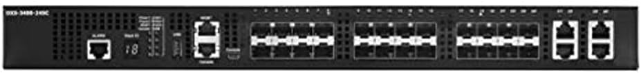
Figure 4.2: Detailed front panel view of the D-Link DXS-3400-24SC switch. From left to right, the front panel includes system status LEDs (Power, Alarm, Link/Act), a console port (RJ-45), a USB port, and then the twenty (20) SFP+ ports followed by four (4) combo RJ45/SFP+ ports. Each port has its own link/activity LED.

Figure 4.3: Rear panel view of the D-Link DXS-3400-24SC switch. This view highlights the modular power supply bays, typically supporting redundant power supplies for enhanced reliability. Multiple cooling fan modules are also visible, designed for efficient heat dissipation. The grounding screw is located on the left side.
5. Setup
5.1 Rack Mounting
- Attach the provided mounting brackets to the sides of the switch using the screws included in the rack mounting kit.
- Align the switch with an available U-space in your standard 19-inch equipment rack.
- Secure the switch to the rack using appropriate rack screws. Ensure the switch is level and firmly seated.
5.2 Connecting Power
- Connect one end of the AC power cord to the power inlet on the rear of the switch.
- Connect the other end of the AC power cord to a grounded electrical outlet.
- Ensure the power switch (if present) is in the ON position. The power LED on the front panel should illuminate.
5.3 Initial Configuration Access
The switch can be configured via a console port or through its default IP address via a network connection.
Console Port Connection:
- Connect the provided console cable (RJ-45 to DB-9) from the switch's console port to a serial port on your computer.
- Open a terminal emulation program (e.g., PuTTY, Tera Term) on your computer.
- Configure the serial port settings: Baud Rate: 115200, Data Bits: 8, Parity: None, Stop Bits: 1, Flow Control: None.
- Press Enter to access the command-line interface (CLI).
Web-based Management:
Refer to the D-Link documentation for the default IP address and login credentials to access the web-based management interface.
6. Operating Instructions
Once the switch is powered on and initially configured, it will begin forwarding traffic according to its default settings or your custom configurations.
6.1 Port Connectivity
- Connect 10GbE SFP+ transceivers into the SFP+ ports for fiber optic connections.
- For the combo ports, use either an SFP+ transceiver or an RJ45 Ethernet cable for 10GBASE-T connections. Note that only one interface (SFP+ or RJ45) can be active per combo port at a time.
- Observe the Link/Activity LEDs on the front panel. A solid green LED indicates a successful link, and a blinking LED indicates data activity.
6.2 Management Interface
The switch can be managed via its web-based GUI, CLI (Command Line Interface) through the console port or Telnet/SSH, and SNMP (Simple Network Management Protocol).
- Web GUI: Access via a web browser using the switch's IP address. Provides a graphical interface for configuration and monitoring.
- CLI: Offers granular control and advanced configuration options. Accessible via console or SSH/Telnet.
- SNMP: Allows integration with network management systems for centralized monitoring.
Refer to the D-Link DXS-3400 Series User Manual (available on the D-Link support website) for detailed instructions on advanced configuration topics such as VLANs, QoS, routing protocols, and stacking.
7. Maintenance
7.1 Cleaning
- Ensure the switch is powered off and disconnected from all power sources before cleaning.
- Use a soft, dry cloth to wipe the exterior of the switch.
- For dust accumulation in ventilation openings, use compressed air. Do not use liquid cleaners or aerosol sprays.
7.2 Firmware Updates
Regularly check the D-Link support website for the latest firmware updates. Firmware updates can provide new features, performance improvements, and security patches.
- Download the latest firmware file from the official D-Link support website.
- Access the switch's web-based management interface or CLI.
- Follow the instructions in the firmware upgrade section of the switch's user manual to perform the update. Warning: Do not power off the switch during a firmware upgrade.
8. Troubleshooting
This section provides solutions to common issues you may encounter with the DXS-3400-24SC switch.
| Problem | Possible Cause | Solution |
|---|---|---|
| Switch does not power on. | No power, faulty power cord, power supply issue. |
|
| No link light on a connected port. | Incorrect cable, faulty transceiver, port disabled, incompatible speed/duplex. |
|
| Cannot access web management interface. | Incorrect IP address, network connectivity issue, firewall, browser issue. |
|
For further assistance, consult the full D-Link DXS-3400 Series User Manual or contact D-Link Technical Support.
9. Specifications
| Feature | Detail |
|---|---|
| Model Number | DXS-3400-24SC |
| Brand | D-Link |
| Ports | 20 x 10GbE SFP+ ports, 4 x 10GbE Combo (RJ45/SFP+) ports |
| Switch Type | Lite Layer 3 Stackable Managed Switch |
| Data Transfer Rate | 12 Gigabits Per Second (per port, aggregate switching capacity will be higher) |
| Interface Type | RJ45, SFP+ |
| Item Weight | 14.66 pounds (6.65 kg) |
| Product Dimensions (LxWxH) | 17.32 x 17.32 x 1.5 inches (44 x 44 x 3.8 cm) |
| Voltage | 240V (AC input range typically wider) |
| Case Material | Plastic (likely metal chassis with plastic components) |
| Operating Temperature | Up to 50 Degrees Celsius |
| Manufacturer | D-Link Systems |
| UPC | 790069423604 |
| First Available Date | November 20, 2014 |
10. Safety Information
Proposition 65 Warning: This product may contain chemicals known to the State of California to cause cancer and birth defects or other reproductive harm. For more information, please visit www.P65Warnings.ca.gov.
Always follow basic safety precautions when using this product to reduce the risk of fire, electric shock, and injury to persons.
- Do not expose the device to water or moisture.
- Do not open the device or attempt to repair it yourself.
- Ensure proper ventilation to prevent overheating.
- Use only the power adapter provided with the device or a D-Link approved replacement.
11. Warranty and Support
For warranty information, technical support, and product registration, please visit the official D-Link website or contact your local D-Link support representative. Keep your purchase receipt as proof of purchase.
D-Link Support Website: www.dlink.com/support


