Schneider Electric CCT15365
Schneider Electric Acti 9 IH Mechanical Time Switch User Manual
Model: CCT15365
1. Product Overview
The Schneider Electric Acti 9 IH mechanical time switch (Model CCT15365) is designed to automatically control electrical loads by switching them On and Off according to a user-defined daily program. This device features a 24-hour switching cycle with a minimum interval of 15 minutes between operations, allowing for up to 48 On and 48 Off switching points per day. It includes a 200-hour battery reserve to maintain program settings during mains power outages and offers a manual override function for temporary control. With a width of 54mm (equivalent to 6 modules of 9mm), it is suitable for standard electrical installations.
Key Features:
- Mechanical time switch for reliable operation.
- 24-hour daily switching cycle.
- Minimum switching time of 15 minutes.
- Up to 48 ON/OFF switching operations per day.
- 200-hour battery reserve for power outage protection.
- Manual override capability.
- Single channel output.
2. Product Components and Views

Figure 2.1: Front view of the time switch, showing the dial and manual override switch.

Figure 2.2: Detailed front view highlighting the 24-hour dial and time setting indicators.

Figure 2.3: Bottom view displaying the screw terminals for electrical connections (L, N, 1, 2, 3).
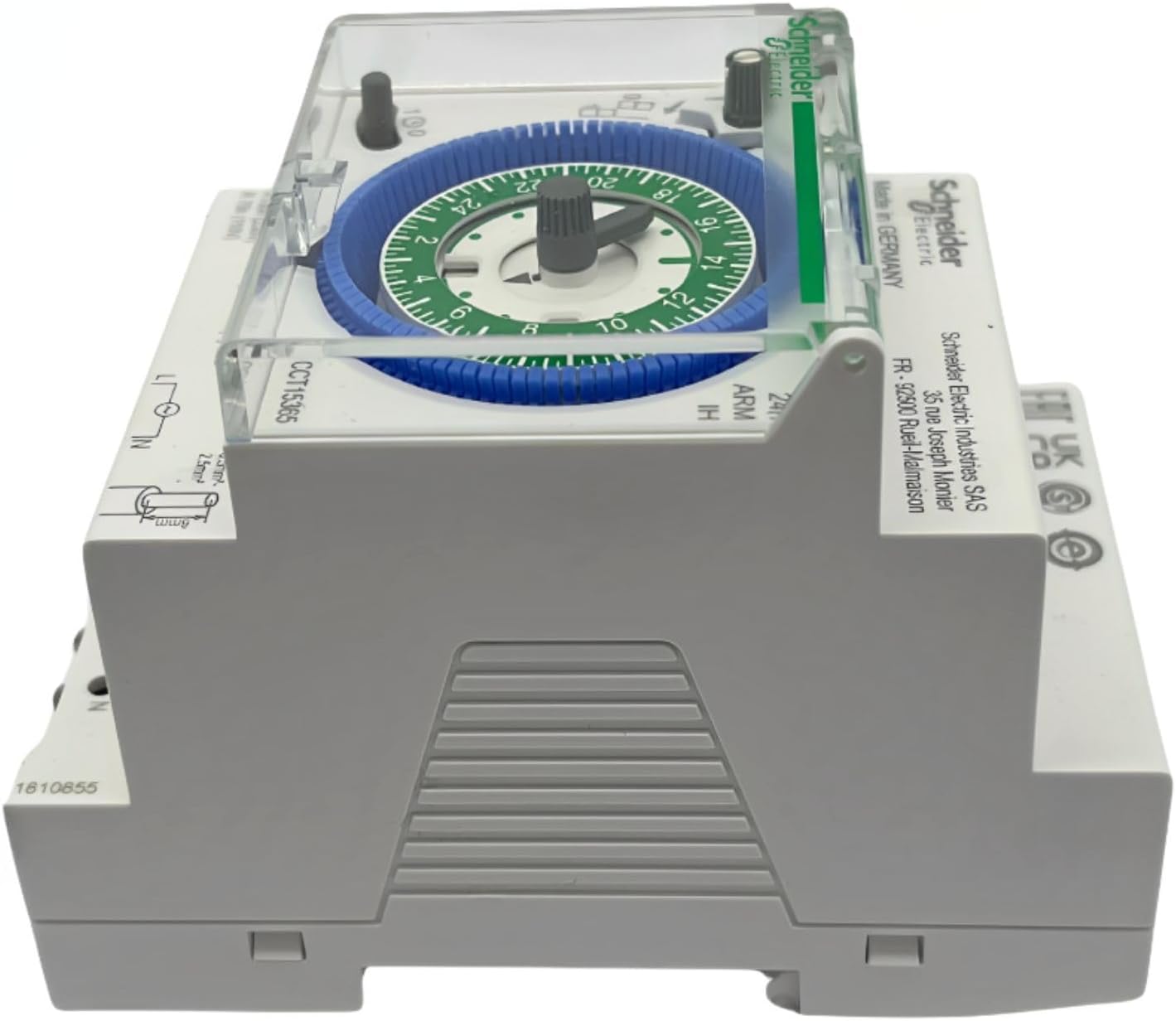
Figure 2.4: Top-down view showing the overall dimensions and mounting points.

Figure 2.5: Side profile of the time switch, illustrating its compact design.

Figure 2.6: Rear view showing the DIN rail mounting mechanism.
3. Setup and Installation
3.1 Safety Precautions
Before proceeding with installation, ensure that the main power supply is disconnected to prevent electric shock. Installation should only be performed by a qualified electrician in accordance with local electrical codes and regulations.
- Always disconnect power before installation or maintenance.
- Verify voltage and current ratings match your application.
- Do not expose the device to moisture or extreme temperatures.
- Ensure proper grounding if required by local codes.
3.2 Mounting
The Acti 9 IH time switch is designed for DIN rail mounting. Locate a suitable position within your electrical panel or enclosure.
- Align the time switch with the DIN rail.
- Press firmly until the device clicks securely into place on the rail.
3.3 Wiring
Refer to the wiring diagram on the device and the following instructions. Use appropriate wire gauges for the rated current (16 Amps).
- Connect the Live (L) input to the terminal marked 'L'.
- Connect the Neutral (N) input to the terminal marked 'N'.
- For the output, connect the switched Live to terminal '1' (Normally Open contact).
- Connect the load to terminal '2' or '3' as per your circuit design. Terminal '2' is typically the common, and '3' is the normally closed contact if applicable, but for this 1-channel switch, '1' is the switched output.
- Ensure all connections are tight and secure to prevent loose contacts and overheating.
3.4 Initial Power-Up
Once wiring is complete, restore power to the circuit. The time switch will begin operating. The internal battery reserve will charge automatically.
4. Operating Instructions
4.1 Setting the Current Time
The time switch features a 24-hour dial. To set the current time:
- Rotate the outer dial clockwise until the current time aligns with the time indicator arrow (usually a small triangle or line on the fixed part of the switch).
- Ensure accuracy for precise scheduling.
4.2 Programming the Timer
The dial has segments (pins) around its circumference, each representing 15 minutes. To program the ON/OFF times:
- To set an ON period: Push the pins outwards for the desired duration. When the dial rotates to these pushed-out segments, the switch will turn ON.
- To set an OFF period: Leave the pins in their inward position for the desired duration. When the dial rotates to these inward segments, the switch will turn OFF.
- Each pin represents 15 minutes. For example, to set a 1-hour ON period, push out 4 consecutive pins.
- You can set up to 48 ON and 48 OFF switching points within the 24-hour cycle.
4.3 Manual Override
The time switch includes a manual override switch, typically a small lever or button, allowing you to temporarily change the output state regardless of the programmed schedule.
- Locate the manual override switch (often labeled with an 'I' for ON and 'O' for OFF, or a hand symbol).
- Move the switch to the desired position (ON or OFF).
- The manual override will remain active until the next programmed switching point, at which time the timer will resume its automatic operation.
4.4 Battery Reserve
The integrated battery reserve provides up to 200 hours of power to maintain the time and program settings during mains power failures. The battery charges automatically when the device is connected to the mains supply.
5. Maintenance
The Schneider Electric Acti 9 IH mechanical time switch requires minimal maintenance.
5.1 Cleaning
- Ensure power is disconnected before cleaning.
- Wipe the exterior of the device with a soft, dry cloth.
- Do not use abrasive cleaners, solvents, or excessive moisture, as these can damage the unit.
5.2 Battery
The internal battery reserve is designed for long-term operation and is not user-replaceable. If the time switch consistently loses time or program settings during power outages, it may indicate a depleted internal battery, and the unit may need professional inspection or replacement.
6. Troubleshooting
| Problem | Possible Cause | Solution |
|---|---|---|
| Device does not turn ON/OFF as programmed. | Incorrect time setting. Pins not correctly pushed/pulled. Manual override engaged. | Verify current time setting. Check all program pins are correctly set for ON/OFF. Disengage manual override if active. |
| Load does not receive power. | No power to the time switch. Incorrect wiring. Faulty load or circuit breaker. | Check main power supply and circuit breaker. Verify wiring connections (L, N, Output). Test the load and circuit breaker independently. |
| Time switch loses time or program during power outage. | Depleted internal battery reserve. | Allow the device to be connected to mains power for several hours to recharge the battery. If the issue persists, the unit may require replacement. |
| Dial is stiff or difficult to turn. | Dust or debris. Mechanical wear. | Gently clean the dial area. If stiffness persists, do not force; contact support. |
7. Technical Specifications
| Specification | Value |
|---|---|
| Model Number | CCT15365 |
| Manufacturer | Schneider Electric |
| Switch Type | Mechanical Time Switch |
| Switching Cycle | 24 hours (Daily) |
| Minimum Switching Time | 15 minutes |
| Number of ON/OFF Operations | Up to 48 ON and 48 OFF |
| Battery Reserve | 200 hours |
| Voltage | 230 Volts (AC) / 250 Volts |
| Amperage Capacity | 16 Amps |
| Contact Type | Normally Open (1 channel) |
| Connector Type | Screw Terminals |
| Mounting Type | DIN Rail |
| Product Dimensions | 10.5 x 7 x 8 cm |
| Item Weight | 140 g |
| Material | Plastic |
| Color | White |
| Certification | CE |
8. Warranty and Support
Schneider Electric products are manufactured to high quality standards. For specific warranty information, please refer to the warranty card included with your product or visit the official Schneider Electric website. In case of technical issues or for further assistance, please contact Schneider Electric customer support through their official channels.
For more information and support, visit the Schneider Electric official website.
Related Documents - CCT15365
 |
Schneider Electric IH 24h Mechanical Time Switch Operating Instructions Operating instructions for the Schneider Electric IH 24h mechanical time switch, covering installation, setting the time and switching times, technical data, and safety precautions. |
 |
Optimisez vos Tableaux Électriques Tertiaires : Solutions Schneider Electric Découvrez les solutions innovantes de Schneider Electric pour optimiser vos tableaux électriques tertiaires, incluant les nouvelles gammes PowerTag Energy, HeatTag, et Acti9 Active pour une gestion énergétique et une sécurité accrues. |
 |
Schneider Electric A9F04110 iC60N-C10-1 10A 1-Pole Circuit Breaker Technical Specifications and Installation Guide Detailed technical specifications, environmental data, sustainability information, and installation guidelines for the Schneider Electric A9F04110 iC60N-C10-1 10A 1-pole circuit breaker. Includes safety warnings and product compliance details. |
 |
Selectivity, Cascading, and Coordination Guide for Low-Voltage Electrical Installations This comprehensive guide from Schneider Electric details the principles and applications of selectivity, cascading, and coordination in low-voltage electrical systems. It provides essential technical information, standards, and selection tables for various Schneider Electric circuit breakers and protection devices to ensure system safety and reliability. |
 |
Electrical Distribution Panel Wiring Diagram with Schneider Electric and ZUBR Components Technical diagram illustrating the wiring of an electrical distribution panel, featuring Schneider Electric circuit breakers (IK60N C40A, C16A, C10A), an RCD (IID 63A 30mA), and a ZUBR 02-63 timer/control module. Includes main power input, busbar connections (L1, L2, L3, N, PE), and detailed wiring routes for phase, neutral, and earth conductors. |
 |
Schneider Electric A9F03110 iC60N-B10-1 Miniature Circuit Breaker Datasheet Technical specifications and product characteristics for the Schneider Electric A9F03110 iC60N-B10-1 single-pole miniature circuit breaker. Includes details on electrical ratings, tripping characteristics, certifications, and environmental specifications. |
Ask a question about this manual
Ask about setup, troubleshooting, compatibility, parts, safety, or missing instructions. Manuals+ will review the question and use this page’s manual context to help answer it.