
1. Introduction
This instruction manual provides important information for the safe and efficient use of your Wiltec Lawn Mower Lift, Model 50800. This device is designed to safely lift lawn tractors, quads, and golf carts up to a maximum weight of 400 kg, allowing for easier maintenance, cleaning, and repair tasks. Please read this manual thoroughly before assembly, setup, or operation to ensure proper use and to prevent injury or damage.

Image 1.1: A lawn mower safely lifted by the Wiltec jack for cleaning.
2. Safety Instructions
Always prioritize safety when operating the lift. Failure to follow these instructions may result in serious injury or property damage.
- Maximum Load Capacity: Do not exceed the maximum load capacity of 400 kg.
- Stable Surface: Always operate the lift on a firm, level, and stable surface. Avoid soft ground, slopes, or uneven terrain.
- Vehicle Stability: Ensure the vehicle is properly positioned and stable on the anti-slip stop before lifting.
- Safety Pin: Always insert the safety pin after lifting the vehicle to the desired height to prevent accidental lowering.
- Clear Area: Keep hands, feet, and other body parts clear of moving parts during operation. Ensure no one is under the vehicle while it is being lifted or lowered.
- Personal Protective Equipment: Wear appropriate safety gear, such as gloves and safety shoes, when operating the lift.
- Inspection: Before each use, inspect the lift for any signs of damage, wear, or loose components. Do not use if damaged.
- Children and Pets: Keep children and pets away from the work area.
- Controlled Lowering: Lower the vehicle slowly and in a controlled manner.

Image 2.1: Proper use of the safety pin to secure the lifted position.
3. Product Features
The Wiltec Lawn Mower Lift offers several features designed for convenience and safety:
- Secure and Practical Lifting: Ideal for lawn tractors, golf carts, and quads, ensuring safe lifting up to 400 kg for repairs, cleaning, and maintenance.
- Ball-Bearing Crank Handle: The crank handle with ball bearings allows for smooth and effortless lifting. Clockwise rotation raises the vehicle, while counter-clockwise rotation lowers it in a controlled manner.
- Stable Anti-Slip Stop: The vehicle's tire rests on an anti-slip stop, ensuring stability during maintenance and preventing unwanted movement.
- Foldable and Compact Design: The foldable structure makes the lift easy to store and transport, occupying minimal space while providing excellent robustness and functionality.
- Adjustable Tilt Angle: The adjustable tilt angle of up to 35° provides convenient access to all parts of the vehicle, ideal for thorough cleaning and precise maintenance.

Image 3.1: Key components and features of the lift.

Sliding Crank

Reinforced Connections

Anti-Slip Stop

Foldable Design
4. Specifications
| Brand | Wiltec |
| Model Number | 50800 |
| Material | Alloy Steel |
| Load Capacity | 400 kg |
| Max Lifting Height | 195 cm |
| Adjustable Tilt Angle | Up to 35° |
| Product Dimensions | 114 x 49.5 x 103 cm |
| Item Weight | 8.12 kg |
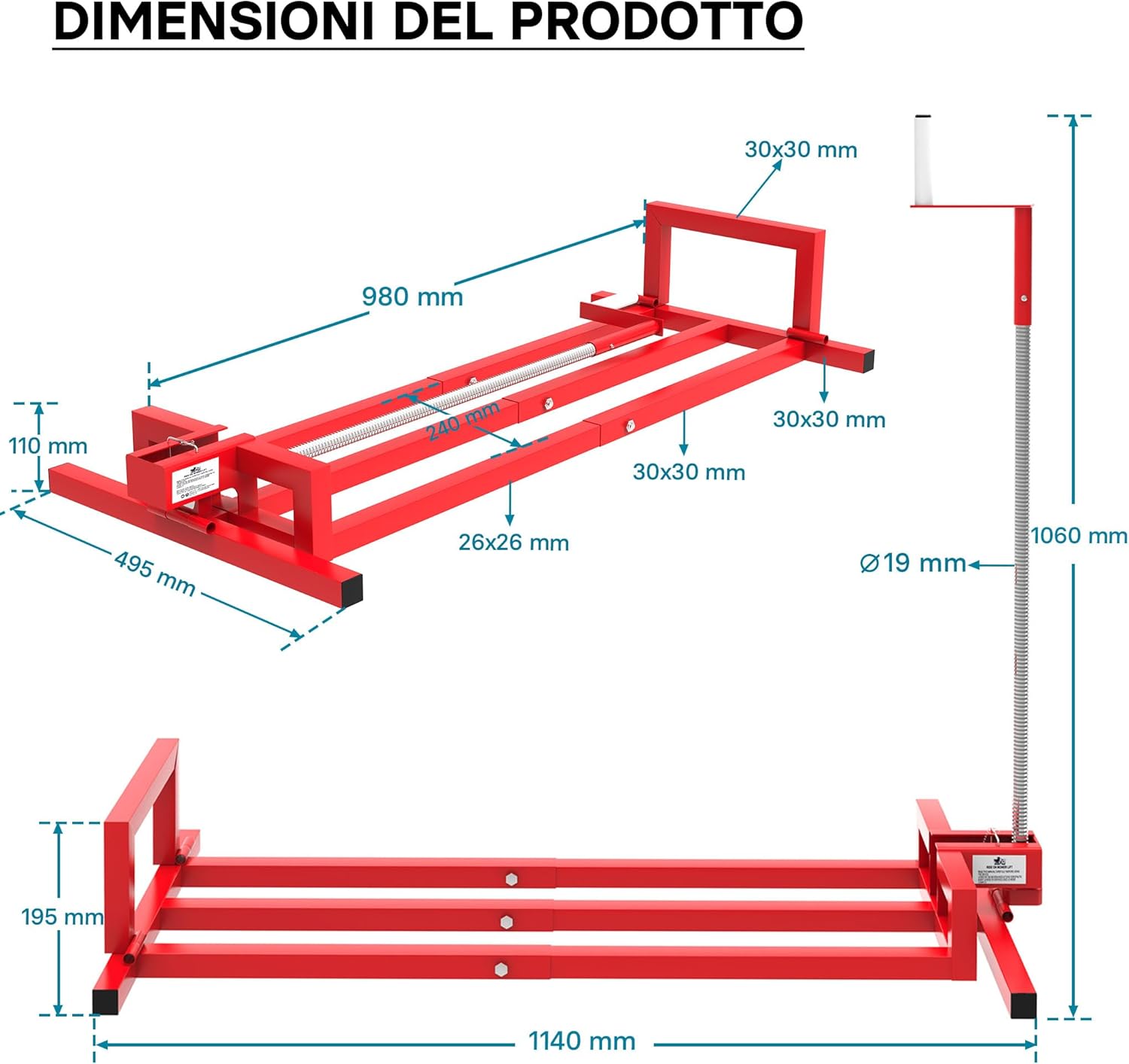
Image 4.1: Product dimensions for the Wiltec Lawn Mower Lift.

Image 4.2: The lift supporting a 400kg load, illustrating its capacity.
5. Assembly
The Wiltec Lawn Mower Lift is designed for straightforward assembly. Follow these general steps:
- Unpack all components and verify against the parts list (if provided separately).
- Extend the main frame of the lift to its full working width.
- Secure the frame sections using the provided bolts and nuts. Ensure all connections are tight.
- Attach the crank mechanism and vertical support bar.
- Ensure the anti-slip stop is correctly positioned and secured.
- Familiarize yourself with the safety pin and its proper insertion.
Note: While specific assembly instructions are not detailed here, refer to the diagrams and ensure all parts are securely fastened before first use.
6. Setup
Before lifting any vehicle, proper setup is essential:
- Choose a Location: Select a flat, stable, and non-slip surface for operation.
- Position the Lift: Place the lift directly behind the vehicle's wheel that you intend to lift.
- Vehicle Preparation: Ensure the vehicle is turned off, the parking brake is engaged (if applicable), and the transmission is in neutral or park.
- Wheel Placement: Carefully roll the vehicle's wheel onto the anti-slip stop of the lift. Ensure the wheel is centered and firmly seated.
- Check Clearance: Verify that there is sufficient clearance around the vehicle and the lift for safe operation.
7. Operating Instructions
7.1. Lifting the Vehicle
- With the vehicle's wheel securely on the anti-slip stop, begin turning the crank handle clockwise.
- Continue turning the crank handle. The lift mechanism will engage, and the vehicle will begin to rise.
- Monitor the vehicle's stability throughout the lifting process.
- Once the desired height is reached (up to 35° tilt), insert the safety pin through the designated hole in the vertical support bar to lock the lift in position. This prevents accidental lowering.
- Before performing any work, gently shake the vehicle to confirm it is stable and securely supported by the lift and safety pin.
7.2. Lowering the Vehicle
- Ensure the area around the vehicle is clear.
- Remove the safety pin from the vertical support bar.
- Slowly turn the crank handle counter-clockwise. The vehicle will begin to lower gradually.
- Continue turning until the vehicle's wheel is fully on the ground.
- Once the vehicle is fully lowered, carefully roll it off the lift.

Image 7.1: Visual guide for adjusting the tilt angle and operating the crank.

Image 7.2: The lift in use with a quad bike, demonstrating its versatility.
7.3. Video Demonstration (Similar Product)
The following video demonstrates the operation of a similar lifting mechanism (Farm Jack). While not the exact product, it illustrates the general principle of lifting and lowering using a high-lift jack. Please refer to the specific instructions above for your Wiltec Lawn Mower Lift.
Video 7.3: Demonstration of a Farm Jack, showing general lifting principles. (Note: This video features a similar lifting mechanism, not the exact Wiltec Lawn Mower Lift.)
8. Maintenance
Regular maintenance ensures the longevity and safe operation of your lift:
- Cleaning: After each use, clean the lift to remove dirt, grass, and debris. Use a damp cloth and mild detergent if necessary. Dry thoroughly.
- Lubrication: Periodically lubricate the screw mechanism and moving parts with a suitable grease or oil to ensure smooth operation.
- Storage: When not in use, store the lift in a dry, clean place, away from direct sunlight and extreme temperatures. Its foldable design allows for compact storage.
- Inspection: Regularly check for loose bolts, nuts, or signs of rust, cracks, or deformation. Tighten any loose fasteners and replace damaged parts immediately.
9. Troubleshooting
If you encounter issues with your Wiltec Lawn Mower Lift, refer to the following common problems and solutions:
| Problem | Possible Cause | Solution |
|---|---|---|
| Lift is difficult to operate (crank is stiff) | Lack of lubrication, dirt in mechanism | Clean the screw mechanism and lubricate with grease or oil. |
| Vehicle feels unstable when lifted | Uneven ground, improper wheel placement, safety pin not engaged | Move to a flat, stable surface. Re-position the wheel correctly on the anti-slip stop. Ensure the safety pin is fully inserted. Do not use if instability persists. |
| Lift does not hold position | Safety pin not inserted, damaged mechanism | Always insert the safety pin. If the mechanism is damaged, discontinue use and contact customer support. |
| Excessive noise during operation | Lack of lubrication, loose components | Lubricate moving parts. Check and tighten all bolts and nuts. |
10. Warranty and Support
For warranty information, technical support, or replacement parts, please contact Wiltec customer service. Keep your purchase receipt as proof of purchase.
Contact Information: Please refer to the contact details provided with your product packaging or visit the official Wiltec website.


