1. Introduction
This manual provides detailed instructions for the proper operation and maintenance of your ICOM IC-M710 MF/HF Marine Transceiver. The IC-M710 is a robust and versatile communication device designed for marine environments, offering reliable long-distance communication capabilities.
Key features include:
- Covers all allowed bands between 1.6 and 27.5 MHz.
- General coverage receiver.
- Supports SSB, RTTY, CW, and AM modes.
- Built-in 2182 kHz alarm (optional for General versions).
- RF gain control and audio activated squelch.
- Terminals for frequency/mode control via NMEA interfacing.
- Direct keypad channel selection entry.
- Large, front-mounted speaker.
- Weather fax ready.
- Backlight control.
- CW full break-in and semi break-in capabilities.
2. Safety Information
Please read all instructions carefully before operating the transceiver. Failure to do so may result in injury or damage to the equipment.
- Power Supply: Ensure the transceiver is connected to a stable 12V DC power source suitable for marine electronics. Incorrect voltage can damage the unit.
- Antenna: Always connect a proper antenna before transmitting. Transmitting without an antenna or with a mismatched antenna can damage the final amplifier stage.
- Water Exposure: While designed for marine use, avoid direct exposure to excessive water spray or submersion. The unit has an IP54 rating, meaning it is protected from dust ingress and splashing water.
- Ventilation: Ensure adequate ventilation around the unit to prevent overheating, especially during prolonged transmission.
- Servicing: Do not attempt to open or service the transceiver yourself. Refer all servicing to qualified Icom technicians.
- Electromagnetic Interference: Be aware of potential electromagnetic interference with other electronic devices on board.
3. Product Overview
The ICOM IC-M710 features a user-friendly front panel with essential controls and a clear display for easy operation.

Figure 3.1: Front view of the ICOM IC-M710 MF/HF Marine Transceiver, showing the display, keypad, and control knobs.

Figure 3.2: A closer view of the IC-M710's front panel, highlighting the display and primary control knobs for mode, AGC, NB, SQL, and channel selection.

Figure 3.3: The IC-M710 display showing "EMERGEN" indicating an emergency channel or mode selection, with the keypad visible on the right.

Figure 3.4: An angled perspective of the IC-M710, providing a clear view of the front panel layout and the "EMERGEN" display status.

Figure 3.5: The IC-M710 with its display appearing blank or powered off, showing the overall compact design of the unit.

Figure 3.6: Side view of the ICOM IC-M710, illustrating its depth and robust casing.

Figure 3.7: Another side view of the IC-M710, providing a different angle of its physical dimensions.
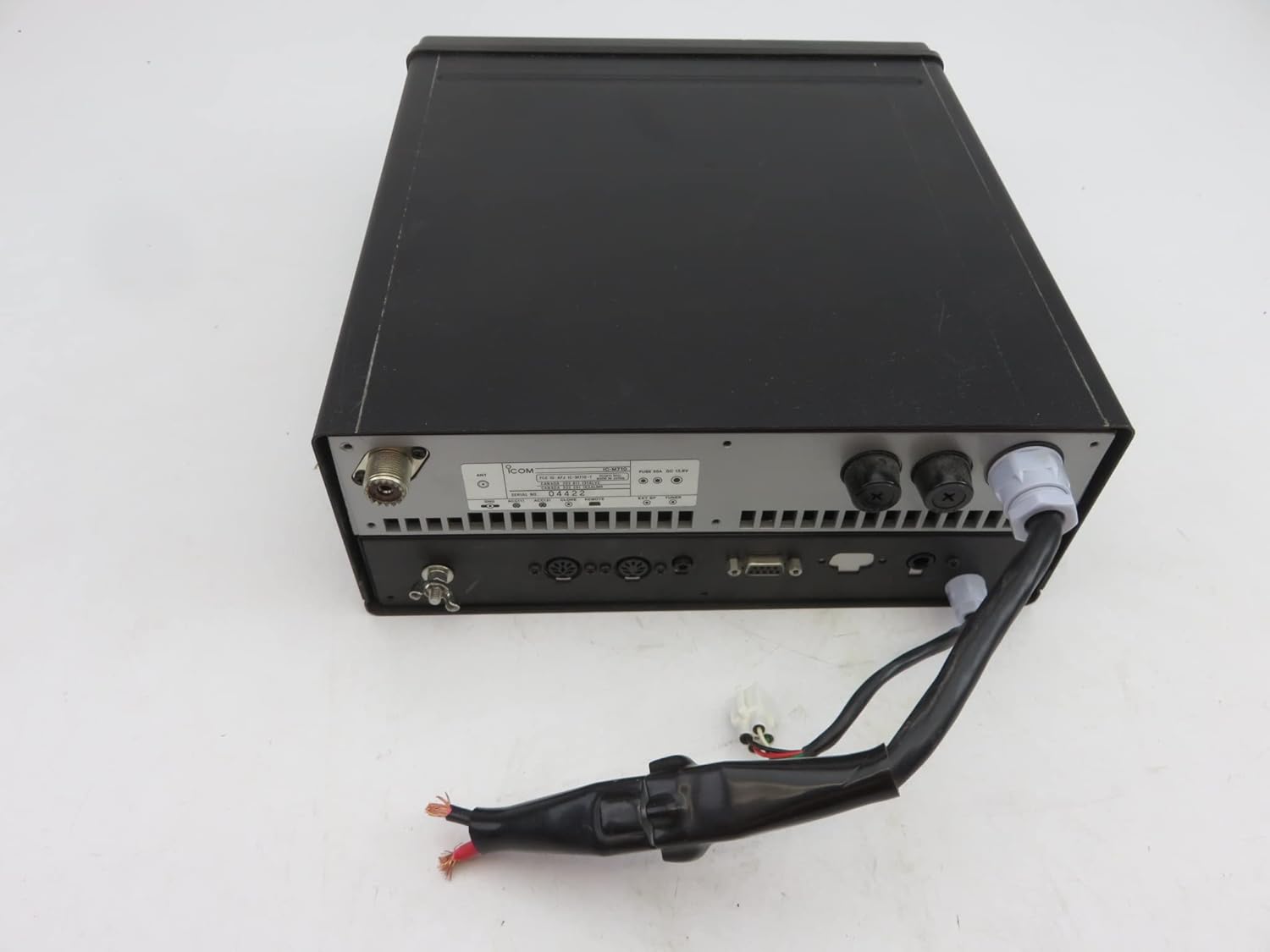
Figure 3.8: Rear view of the ICOM IC-M710, displaying various connection ports for antenna, power, and external devices, with a power cable attached.

Figure 3.9: Bottom view of the IC-M710, showing mounting points and a screwdriver indicating potential access for maintenance or installation.
Front Panel Controls:
- Display: Shows frequency, mode, channel number, and various status indicators.
- Keypad: Numeric keys for direct frequency/channel entry and function keys.
- MODE Knob: Selects operating mode (SSB, RTTY, CW, AM).
- AGC Knob: Adjusts Automatic Gain Control.
- NB Knob: Noise Blanker control.
- SQL Knob: Squelch level adjustment.
- VOLUME Knob: Adjusts audio output level.
- DIMMER Knob: Adjusts display backlight brightness.
- POWER Button: Turns the transceiver on/off.
- 2182kHz RESET Button: Resets the 2182 kHz alarm.
- TX FREQ Button: Toggles between transmit and receive frequency display.
- MICROPHONE Connector: For connecting the supplied microphone.
4. Setup
4.1 Unpacking and Inspection
Carefully unpack the transceiver and all accessories. Verify that all items listed in the packing list are present and undamaged. If any items are missing or damaged, contact your dealer immediately.
4.2 Mounting
The IC-M710 can be mounted in various locations on your vessel. Choose a location that is:
- Away from direct sunlight and excessive heat sources.
- Protected from heavy spray or submersion.
- Accessible for operation and maintenance.
- Provides adequate ventilation around the unit.
Use the supplied mounting bracket and hardware to securely fasten the transceiver. Ensure the mounting surface is strong enough to support the unit's weight (approximately 24.7 pounds).
4.3 Electrical Connections
Power Connection: Connect the supplied DC power cable to the transceiver's power input terminal (refer to Figure 3.8). Connect the other end to a 12V DC power source on your vessel. Ensure correct polarity (red to positive, black to negative) and use appropriate fusing.
Antenna Connection: Connect a suitable MF/HF marine antenna to the antenna connector on the rear panel. Ensure the antenna system is properly tuned for the operating frequencies to prevent damage to the transceiver.
Grounding: For optimal performance and safety, ensure the transceiver chassis is properly grounded to the vessel's ground system.
Optional Connections: Connect any optional accessories such as external speakers, NMEA devices, or remote control units as per their respective manuals.
5. Operating Instructions
5.1 Basic Operation
- Power On: Press the POWER button to turn on the transceiver.
- Volume Adjustment: Rotate the VOLUME knob to a comfortable listening level.
- Squelch Adjustment: Rotate the SQL knob clockwise until the background noise disappears. If no signal is present, rotate it counter-clockwise until noise is heard, then slightly clockwise until it just silences.
- Mode Selection: Rotate the MODE knob to select the desired operating mode (e.g., USB for voice communication).
- Frequency/Channel Selection:
- Direct Entry: Use the numeric keypad to enter the desired frequency or channel number, then press ENTER (if applicable).
- Tuning Knob: Use the TUNE knob to fine-tune the frequency.
- Transmitting: Press and hold the PTT (Push-To-Talk) button on the microphone to transmit. Speak clearly into the microphone. Release the PTT button to receive.
5.2 Advanced Features
- 2182 kHz Alarm: To activate the 2182 kHz alarm, refer to specific maritime regulations and the detailed instructions in the full manual. The 2182kHz RESET button is used to stop the alarm.
- RF Gain Control: Adjust the RF GAIN control to optimize signal reception, especially in strong signal environments.
- Noise Blanker (NB): Use the NB control to reduce pulse-type noise interference.
- Automatic Gain Control (AGC): The AGC control helps maintain a consistent audio output level despite varying signal strengths.
- Weather Fax: The transceiver is capable of receiving weather fax signals. Consult the full manual for setup and operation of this feature, typically requiring external software and a computer.
- NMEA Interfacing: The IC-M710 supports NMEA interfacing for external frequency/mode control. Refer to the detailed wiring diagrams and software requirements in the comprehensive manual.
6. Maintenance
Regular maintenance ensures the longevity and optimal performance of your IC-M710 transceiver.
- Cleaning: Wipe the unit with a soft, dry cloth. For stubborn dirt, use a cloth lightly dampened with fresh water. Avoid using strong chemicals or abrasive cleaners.
- Connectors: Periodically inspect all connectors (antenna, power, microphone) for corrosion or damage. Clean with a contact cleaner if necessary.
- Antenna System: Regularly check your antenna and coaxial cable for physical damage, corrosion, or loose connections. A damaged antenna system can severely impact performance and potentially damage the transceiver.
- Power Supply: Ensure the power supply connections are secure and free from corrosion. Check the fuse periodically.
- Storage: If storing the transceiver for an extended period, disconnect it from power and store it in a dry, cool place.
7. Troubleshooting
Before contacting customer support, please refer to the following common issues and their solutions:
| Problem | Possible Cause | Solution |
|---|---|---|
| No power | Loose power connection, blown fuse, power supply issue. | Check power cable connections. Inspect and replace fuse if blown. Verify power supply voltage. |
| No reception / Weak reception | Antenna not connected, damaged antenna/cable, squelch too high, incorrect frequency/mode. | Ensure antenna is connected. Check antenna and cable for damage. Adjust SQL knob. Verify frequency and mode settings. |
| Cannot transmit | Microphone not connected, PTT button faulty, antenna issue. | Ensure microphone is securely connected. Test PTT button. Check antenna connection and SWR. |
| Distorted audio | Volume too high, poor signal quality, external interference. | Adjust VOLUME. Check signal strength. Try adjusting NB or AGC. |
If the problem persists after attempting these solutions, please contact Icom customer support or an authorized service center.
8. Specifications
| Feature | Specification |
|---|---|
| Model Number | IC-M710 |
| Brand | Icom |
| Package Dimensions | 17.75 x 14.75 x 9.5 inches |
| Item Weight | 24.7 pounds |
| Number of Channels | 1136 |
| International Protection Rating | IP54 |
| First Available Date | October 23, 2014 |
9. Warranty and Support
For warranty information, please refer to the warranty card included with your product or visit the official Icom website. Keep your purchase receipt as proof of purchase for warranty claims.
For technical support, service, or inquiries, please contact Icom customer service. Contact details can typically be found on the Icom official website or in the product packaging.
Icom America Website: www.icomamerica.com