1. Introduction
Thank you for purchasing the Mastech MS8230B Digital Multimeter. This device is a compact, battery-operated, handheld digital multimeter designed for measuring DC and AC voltage, DC current, resistance, diode, and transistor (hFE) tests. It features a large LCD display for easy reading and is built to international safety standards.
Please read this instruction manual thoroughly before using the multimeter to ensure safe and proper operation. Keep this manual for future reference.
2. Safety Information
This multimeter is designed according to IEC 1010-1 international safety standards for electronic measuring instruments. It complies with CAT III 600V and CAT II 1000V overvoltage categories. Always adhere to the following safety precautions:
- Never exceed the maximum input limits for any function.
- Do not use the meter if the case is damaged or open.
- Ensure the test leads are in good condition, without any damaged insulation.
- Always turn off the circuit power and discharge all high-voltage capacitors before measuring resistance, diodes, or hFE.
- Use extreme caution when working with voltages above 60V DC or 30V AC RMS, as these pose a shock hazard.
- Remove test leads from the circuit before changing functions or ranges.
- Replace the battery immediately when the low battery indicator appears to ensure accurate readings.
- Do not operate the meter in explosive gas, vapor, or dust environments.
3. Package Contents
Verify that all items listed below are present and undamaged:
- Mastech MS8230B Digital Multimeter
- Test Leads (one pair)
- 9V Battery (pre-installed or included separately)
- User Manual
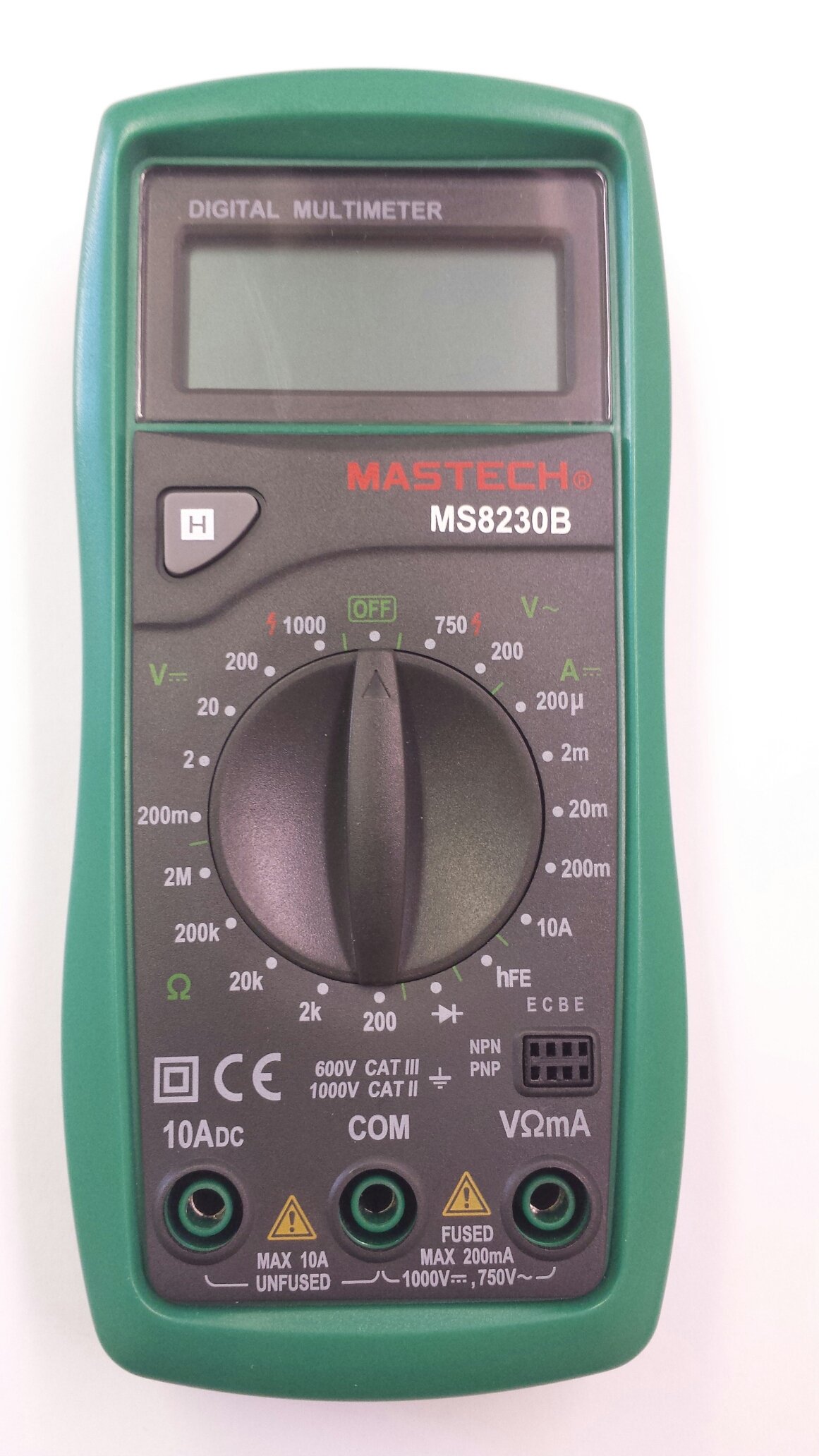
Image 1: Contents of the Mastech MS8230B package, including the multimeter, test leads, batteries, and user manual.
4. Setup
4.1 Battery Installation
The MS8230B multimeter requires one 9V battery for operation. If the battery is not pre-installed or needs replacement:
- Ensure the multimeter is turned OFF and disconnect all test leads.
- Locate the battery compartment cover on the back of the unit.
- Loosen the screw(s) on the battery cover and remove the cover.
- Connect the 9V battery to the battery connector, observing correct polarity.
- Place the battery into the compartment and replace the cover, securing it with the screw(s).
4.2 Connecting Test Leads
Always connect the test leads correctly for the desired measurement:
- Insert the red test lead into the "VΩmA" jack for voltage, resistance, and low current measurements.
- Insert the red test lead into the "10ADC" jack for high DC current measurements (up to 10A).
- Always insert the black test lead into the "COM" (common) jack.
5. Operating Instructions
Before taking any measurement, ensure the test leads are correctly connected and the function switch is set to the appropriate range.
5.1 DC Voltage Measurement (DCV)
- Connect the red test lead to the "VΩmA" jack and the black test lead to the "COM" jack.
- Set the rotary switch to the desired DCV range (e.g., 200mV, 2V, 20V, 200V, 1000V). If the voltage is unknown, start with the highest range and decrease as necessary.
- Connect the test leads across the component or circuit to be measured.
- Read the voltage value on the LCD display. Observe the polarity indication.
5.2 AC Voltage Measurement (ACV)
- Connect the red test lead to the "VΩmA" jack and the black test lead to the "COM" jack.
- Set the rotary switch to the desired ACV range (e.g., 200V, 750V). Start with the highest range if the voltage is unknown.
- Connect the test leads across the component or circuit to be measured.
- Read the voltage value on the LCD display.
5.3 DC Current Measurement (DCA)
Caution: Never attempt to measure current on a circuit with voltage present by connecting the meter in parallel. Always connect the meter in series with the load.
- Determine the expected current. For currents up to 200mA, connect the red lead to "VΩmA". For currents up to 10A, connect the red lead to "10ADC". The black lead always goes to "COM".
- Set the rotary switch to the appropriate DCA range (e.g., 200µA, 2mA, 20mA, 200mA, 10A).
- Turn off the power to the circuit. Open the circuit where the current is to be measured.
- Connect the multimeter in series with the circuit.
- Apply power to the circuit and read the current value on the LCD display.
5.4 Resistance Measurement
Caution: Ensure the circuit under test is completely de-energized and all capacitors are discharged before measuring resistance.
- Connect the red test lead to the "VΩmA" jack and the black test lead to the "COM" jack.
- Set the rotary switch to the desired Resistance (Ω) range (e.g., 200Ω, 2kΩ, 20kΩ, 200kΩ, 2MΩ).
- Connect the test leads across the component to be measured.
- Read the resistance value on the LCD display.
5.5 Diode Test
Caution: Ensure the circuit under test is completely de-energized and all capacitors are discharged before performing a diode test.
- Connect the red test lead to the "VΩmA" jack and the black test lead to the "COM" jack.
- Set the rotary switch to the Diode symbol (→|).
- Connect the red test lead to the anode and the black test lead to the cathode of the diode. The display will show the forward voltage drop (typically 0.5V to 0.8V for silicon diodes).
- Reverse the test leads. The display should show "OL" (Open Loop) for a good diode. A reading in both directions or "0" indicates a shorted diode.
5.6 Transistor hFE Test
Caution: Ensure the transistor is not connected to a live circuit.
- Set the rotary switch to the "hFE" position.
- Identify if the transistor is NPN or PNP.
- Insert the transistor's emitter, base, and collector leads into the corresponding holes in the hFE socket on the multimeter.
- Read the hFE (DC current gain) value on the LCD display.
5.7 Data Hold Function
Press the "H" button to hold the current reading on the display. Press it again to release the hold function and resume live readings.
6. Maintenance
6.1 Cleaning
Wipe the case with a damp cloth and mild detergent. Do not use abrasives or solvents. Keep the jacks free of dust and debris.
6.2 Battery Replacement
When the battery symbol appears on the LCD, the 9V battery needs to be replaced. Refer to section 4.1 for battery installation instructions.
6.3 Fuse Replacement
The multimeter is protected by a fuse. If the current measurement function stops working, the fuse may need replacement. This should only be performed by qualified personnel. The fuse specifications are typically printed near the fuse holder or in the specifications section.
7. Troubleshooting
If the multimeter does not function correctly, check the following:
- No display or faint display: Check the battery. Replace if necessary.
- Incorrect readings: Ensure the test leads are properly connected, the function switch is on the correct range, and the battery is not low.
- "OL" (Overload) displayed: The measured value exceeds the selected range. Switch to a higher range.
- Current measurement not working: Check the fuse.
If problems persist, contact customer support.
8. Specifications
The Mastech MS8230B Digital Multimeter offers the following technical specifications:

Image 2: Detailed specifications for the Mastech MS8230B Multimeter, including display, range, and accuracy.
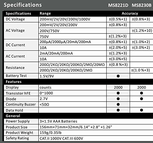
Image 3: Comparison table of specifications for Mastech MS8230B and MS8221D multimeters.
| Specification | Value |
|---|---|
| Display | 1999 counts, 15mm digit height |
| DC Voltage (DCV) | 200mV, 2V, 20V, 200V, 1000V (Accuracy: 0.5% to 0.8%) |
| AC Voltage (ACV) | 200V, 750V (Accuracy: 1.2%) |
| DC Current (DCA) | 200µA, 2mA, 20mA, 200mA, 10A (Accuracy: 1.0% to 2.0%) |
| Resistance (Ω) | 200Ω, 2kΩ, 20kΩ, 200kΩ, 2MΩ (Accuracy: 0.8% to 1.0%) |
| Diode Test | Forward voltage drop |
| Transistor hFE Test | 1 to 1000 |
| Data Hold | Yes |
| Low Battery Indication | Yes |
| Overload Protection | Yes |
| Power Source | 1 x 9V battery |
| Dimensions (L x W x H) | 15.2 x 7.6 x 2.5 cm (approx. 6 x 3 x 1 inches) |
| Weight | Approx. 158.76 g (5.6 ounces) |
| Safety Rating | IEC 1010-1 CAT III 600V, CAT II 1000V |
| Operating Temperature | 0°C to 40°C (32°F to 104°F) |
| Storage Temperature | -10°C to 50°C (14°F to 122°F) |
9. Warranty and Support
Mastech products are designed for reliability and performance. For specific warranty details, please refer to the warranty card included with your product or contact your local Mastech distributor.
For technical support or service inquiries, please contact Mastech customer service through their official website or the contact information provided with your purchase documentation.