Product Overview
The DB Electrical SSW2829 Key Switch is a replacement component designed for various lawn and garden equipment. This key switch facilitates the ON-OFF operation of compatible engines and systems, ensuring proper electrical control. It is built to meet OEM specifications for reliable performance.

Image 1: The DB Electrical SSW2829 Key Switch, shown with two accompanying keys. This view highlights the main body of the switch and the key insertion point.
Compatibility and Specifications
This key switch is compatible with a range of equipment, including specific models from AYP, Briggs & Stratton, Exmark, and Troy Bilt. Always verify part fitment before installation.
Replaces OEM Numbers:
- ARROWHEAD: SSW2829
- AYP / ROPER: 102972X, 145499, 158913
- BRIGGS & STRATTON: 490066, 493625
- EXMARK: 1-543070
- HUSQVARNA: 532102972, 532145499, 532158913
- J & N: 240-22159
- NOMA: 305720
- STENS: 430-173
- TROY BILT: 1754250, 1754250P
Technical Specifications:
| Unit Type | SWITCH - KEY |
| Operation Mode | ON-OFF |
| Contact Type | Normally Open |
| Connector Type | Clamp |
| Product Dimensions (L x W x H) | 2.4 x 2.4 x 2.3 inches |
| Item Weight | 3.2 ounces |
| International Protection Rating | IP00 |
Installation (Setup)
Proper installation is crucial for the safe and effective operation of the key switch. If you are unsure about any step, consult a qualified technician.
- Safety First: Before beginning any installation, ensure the equipment's power source is completely disconnected (e.g., remove spark plug wire, disconnect battery).
- Locate Existing Switch: Identify the current key switch on your equipment. Note its position and how it is mounted.
- Disconnect Wiring: Carefully label and disconnect all wires connected to the old switch. Take photos if necessary to aid reassembly.
- Remove Old Switch: Unmount the old key switch from its housing.
- Verify New Switch: Compare the new DB Electrical SSW2829 switch with the old one to ensure it is the correct replacement part, paying attention to the number and configuration of terminals.
- Install New Switch: Mount the new SSW2829 key switch into the equipment's panel or housing. Secure it firmly.
- Connect Wiring: Reconnect the wires to the corresponding terminals on the new switch, following your labels or photos. Ensure all connections are secure and free from corrosion.
- Test Functionality: Reconnect the equipment's power source. Insert the key and test the switch's ON-OFF operation to ensure the engine starts and stops correctly.
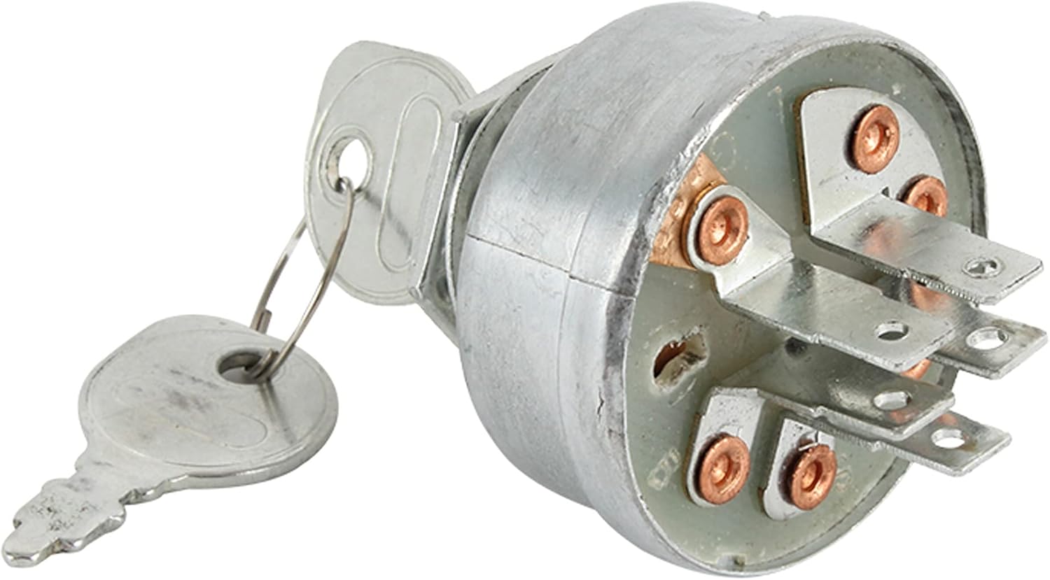
Image 2: Rear view of the key switch, displaying the multiple electrical terminals. These terminals are crucial for connecting the switch to the equipment's wiring harness.

Image 3: Side view of the key switch with a key inserted, illustrating the mounting nut and washer. This perspective shows how the switch is secured in place.
Operating Instructions
The DB Electrical SSW2829 Key Switch operates as a standard ignition switch for your equipment.
- Insert Key: Insert the provided key into the key slot of the switch.
- Turn to ON: Rotate the key clockwise to the "ON" position to activate the equipment's electrical system.
- Start Engine: Continue rotating the key to the "START" position (if applicable) to engage the starter motor and crank the engine. Release the key once the engine starts; it will typically return to the "ON" position.
- Turn to OFF: To shut down the equipment, rotate the key counter-clockwise to the "OFF" position. Remove the key when the equipment is not in use to prevent unauthorized operation.
Maintenance
Regular maintenance helps prolong the life of your key switch and ensures reliable operation.
- Keep Clean: Periodically clean the exterior of the switch and the key slot to prevent dirt and debris buildup. Use a dry cloth.
- Inspect Connections: Annually, or if issues arise, inspect the electrical connections at the back of the switch for corrosion, looseness, or damage. Ensure they are clean and secure.
- Avoid Force: Do not force the key into the switch or apply excessive force when turning. This can damage the internal mechanism.
- Store Keys Safely: Keep spare keys in a secure location.
Troubleshooting
If you encounter issues with your key switch, consider the following common problems and solutions:
| Problem | Possible Cause | Solution |
|---|---|---|
| Engine does not start when key is turned. | Loose or corroded electrical connections. Faulty starter solenoid or battery. Incorrect key switch installed. | Check and secure all wiring connections to the switch and battery. Clean any corrosion. Test battery and starter solenoid. Verify the switch is the correct model for your equipment. |
| Key is difficult to turn or remove. | Debris in key slot. Worn key or internal switch mechanism. | Clean the key slot with compressed air. Try a different key if available. If the issue persists, the switch mechanism may be worn and require replacement. |
| Engine does not shut off when key is turned to OFF. | Faulty switch internal contacts. Wiring issue. | Inspect wiring for shorts or incorrect connections. The switch itself may be defective and require replacement. |
Warranty Information
DB Electrical provides a 1-year warranty on this product from the date of purchase. This warranty covers defects in materials and workmanship. If the product does not perform as expected within this period, contact DB Electrical for assistance or a replacement. This warranty is subject to the terms and conditions outlined by DB Electrical.
Support
For further assistance, technical support, or warranty claims, please contact DB Electrical directly. You can find more information and contact details by visiting the official DB Electrical store or website.
DB Electrical Store: Visit DB Electrical Store on Amazon


