1. Introduction
The Seeed Studio CAN-BUS Shield V1.2 is an expansion board designed to provide CAN (Controller Area Network) capabilities to Arduino and Seeeduino microcontrollers. This shield allows your microcontroller to communicate with other CAN-enabled devices, making it suitable for automotive applications, industrial automation, and other projects requiring robust, real-time communication.
It integrates the MCP2515 CAN controller and MCP2551 CAN transceiver, offering a reliable and efficient solution for CAN communication. The shield is compatible with Arduino UNO (ATmega328), Arduino Mega (ATmega1280/2560), and Arduino Leonardo (ATmega32U4).

Figure 1: Top view of the Seeed Studio CAN-BUS Shield V1.2. This image displays the main components including the DB9 connector, CAN controller, and various headers, along with key specifications like voltage (4.8~5.2V), size (68*53mm), and net weight (50g).
2. Features
- Implements CAN V2.0B at up to 1 Mb/s.
- Industrial standard 9-pin Sub-D connector (DB9) for CAN connection.
- Two Grove connectors (I2C and UART) for easy expansion.
- SPI interface up to 10 MHz.
- Standard (11-bit) and extended (29-bit) data and remote frames.
- Two receive buffers with prioritized message storage.
- Operating voltage: 4.8V to 5.2V.
- On-board 120Ω terminator resistor, selectable via jumper.
- LED indicators for power, TX, RX, and INT.
- Compatible with Arduino UNO, Arduino Mega, and Arduino Leonardo.
3. Specifications
| Parameter | Value |
|---|---|
| Model Number | E00469 |
| CAN Controller | MCP2515 |
| CAN Transceiver | MCP2551 |
| Operating Voltage | 4.8V - 5.2V |
| Dimensions | 68mm x 53mm (approx. 2.68 x 2.09 inches) |
| Net Weight | 50g (approx. 1.76 ounces) |
| Connectivity | CAN bus, SPI, I2C, UART |
| Compatible Microcontrollers | Arduino UNO, Mega, Leonardo; Seeeduino |
4. Hardware Overview
The CAN-BUS Shield V1.2 features several key components and connectors for its functionality. Understanding these components is crucial for proper setup and operation.
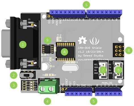
Figure 2: Labeled diagram of the CAN-BUS Shield V1.2 components.
- DB9 Connector: Standard 9-pin D-sub connector for CAN bus connection.
- Terminator Resistor Jumper (J1): Used to enable or disable the 120Ω termination resistor. Set to ON for bus termination, OFF otherwise.
- Power LED: Indicates when the shield is powered on.
- CANH/CANL Terminal Block (J10): Alternative connection point for CAN_H and CAN_L signals.
- Arduino Compatible Headers: Standard headers for connecting to Arduino/Seeeduino boards.
- UART Grove Connector: For connecting Grove modules with UART interface.
- I2C Grove Connector: For connecting Grove modules with I2C interface.
- SPI Interface Pins (JP3): Pins for SPI communication (VCC, MISO, MOSI, CSK, GND, AST). Located on the bottom side of the board.
- MCP2551 CAN Transceiver (U1): Converts the digital signals from the MCP2515 to the differential signals required for the CAN bus.
- MCP2515 CAN Controller (U2): Handles the CAN protocol, including message transmission and reception.
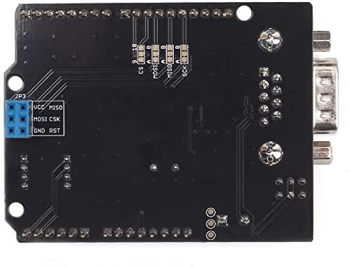
Figure 3: Bottom view of the CAN-BUS Shield V1.2, highlighting the JP3 SPI interface pins.
5. Pinout and Connections
Understanding the pin assignments is essential for correct integration and communication. The shield utilizes SPI for communication with the microcontroller and provides various connection options for the CAN bus.
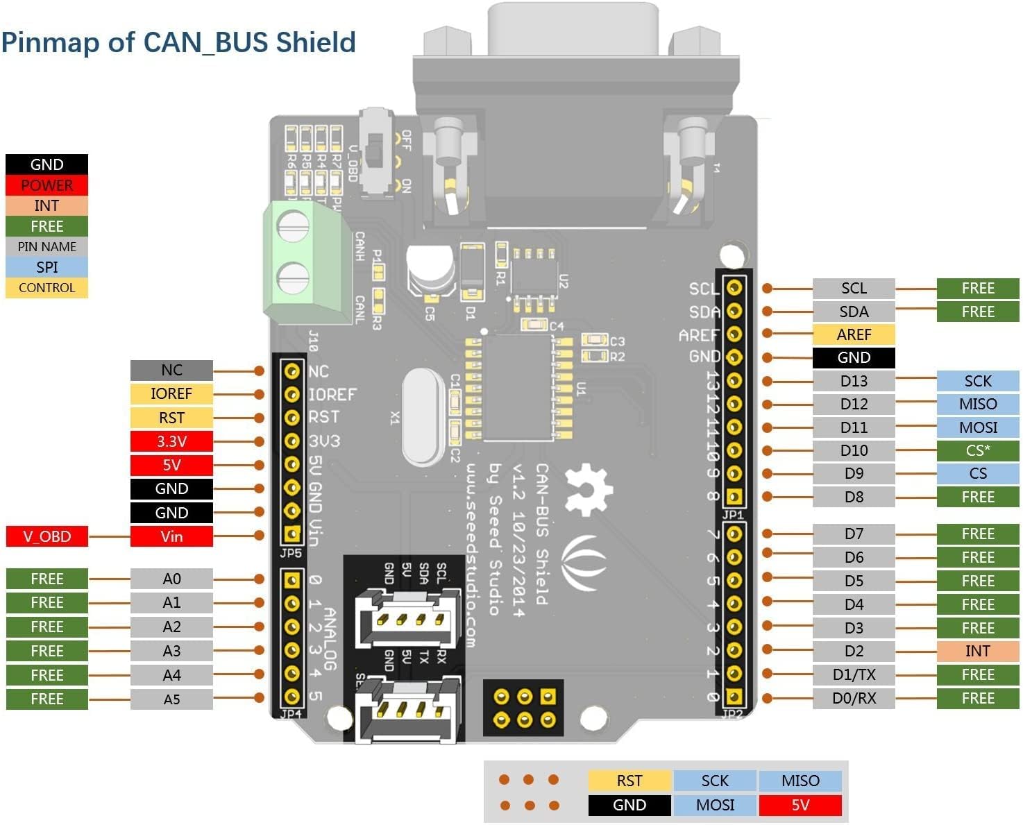
Figure 4: Detailed pinmap of the CAN-BUS Shield V1.2, showing connections to the Arduino headers and internal pin assignments.
5.1. SPI Communication Pins
The CAN-BUS Shield communicates with the Arduino via the SPI interface. The default Chip Select (CS) pin is D9. Ensure your software configuration matches this pin. Some newer versions or libraries might default to D10, so verify if you encounter communication issues.
- SCK: D13
- MISO: D12
- MOSI: D11
- CS: D9 (Default)
- INT: D2 (Interrupt pin)
5.2. CAN Bus Connections (DB9 and Terminal Block)
The CAN bus can be connected via the DB9 connector or the screw terminal block (J10). The standard pinout for the DB9 connector is crucial for proper communication, especially in automotive applications (OBD-II).

Figure 5: OBD-II connector wiring diagram. This illustrates how to connect the CAN-BUS Shield to an OBD-II port, showing connections for GND, CAN_H, CAN_L, and V_OBD.
DB9 Pinout (Common for OBD-II):
- Pin 2: CAN_L (Low)
- Pin 7: CAN_H (High)
- Pin 6: GND
- Pin 16: V_OBD (Vehicle Power)
Note: Some DB9 connectors may have non-standard pinouts. Always verify the pin assignments of your specific CAN device to ensure correct wiring. The screw terminal block (J10) provides direct access to CAN_H and CAN_L for custom wiring.
6. Setup
6.1. Physical Connection to Arduino/Seeeduino
- Align the CAN-BUS Shield with the headers on your Arduino or Seeeduino board.
- Carefully press the shield onto the microcontroller board, ensuring all pins are correctly seated.
- Important Note for Arduino UNO: Due to the physical layout, the shield may come into contact with the USB connector or DC power jack on some Arduino UNO boards. If this occurs, it can cause short circuits or prevent proper seating. Consider using longer pin headers or a small spacer to elevate the shield slightly if necessary. Do not force the shield if it clashes with components.
- Important Note for Arduino Mega: This version of the shield is designed to work with Arduino Mega without needing to bend or clip any pins. Ensure proper alignment.
6.2. CAN Bus Termination
The CAN bus requires termination resistors at both ends of the bus to prevent signal reflections. The CAN-BUS Shield includes a selectable 120Ω terminator resistor.
- If your CAN-BUS Shield is at one end of the CAN bus, set the J1 jumper to the ON position to enable the 120Ω termination resistor.
- If your CAN-BUS Shield is in the middle of the CAN bus, or if termination is provided by another device, set the J1 jumper to the OFF position.
6.3. Software Setup
- Download and install the appropriate CAN-BUS library for Arduino (e.g., the Seeed Studio CAN-BUS library). This can typically be found in the Arduino IDE's Library Manager or on the Seeed Studio website.
- Include the library in your Arduino sketch.
- Initialize the CAN controller in your code, specifying the SPI Chip Select (CS) pin (default D9) and the desired CAN bus speed.
7. Operating Instructions
Once the shield is physically connected and the software library is installed, you can begin sending and receiving CAN messages.
7.1. Sending CAN Messages
To send a CAN message, you will typically use functions provided by the CAN-BUS library. These functions allow you to specify the CAN ID (standard or extended), the data length, and the data bytes to be transmitted.
- Define the CAN ID and data payload.
- Use the library's transmit function (e.g.,
CAN.sendMsgBuf()) to send the message. - Monitor the TX LED on the shield to confirm transmission activity.
7.2. Receiving CAN Messages
The shield can receive CAN messages and store them in its internal buffers. You can configure filters to only receive messages with specific CAN IDs.
- Check for available messages using the library's receive function (e.g.,
CAN.readMsgBuf()). - Read the received CAN ID, data length, and data bytes.
- Monitor the RX LED on the shield to confirm reception activity.
- The INT pin (D2) can be used to trigger an interrupt on the microcontroller when a new CAN message is received, allowing for efficient, event-driven processing.
8. Maintenance
The CAN-BUS Shield is a robust electronic component that requires minimal maintenance. Follow these guidelines to ensure its longevity and reliable operation:
- Storage: Store the shield in a dry, anti-static environment when not in use.
- Cleaning: If necessary, gently clean the board with a soft, dry brush or compressed air to remove dust. Avoid using liquids or abrasive materials.
- Handling: Handle the board by its edges to avoid touching components, especially the pins, which can be sensitive to static discharge.
- Power Supply: Ensure a stable power supply within the specified operating voltage range (4.8V - 5.2V) to prevent damage.
9. Troubleshooting
If you encounter issues with your CAN-BUS Shield, consider the following troubleshooting steps:
- No Power/LEDs Off:
- Ensure the shield is correctly seated on the Arduino/Seeeduino board.
- Verify that the Arduino/Seeeduino is powered on and receiving adequate voltage.
- Check for any physical shorts, especially if the shield is clashing with the USB port or DC jack of an Arduino UNO.
- CAN Communication Failure:
- Wiring: Double-check your CAN_H and CAN_L connections. Ensure they are not reversed and are correctly connected to the CAN bus. Verify the DB9 pinout if using an external device.
- Termination: Confirm that the 120Ω termination resistor jumper (J1) is set correctly (ON at bus ends, OFF in the middle).
- SPI Connection: Ensure the SPI pins (SCK, MISO, MOSI, CS) are correctly connected and that the Chip Select (CS) pin in your software matches the hardware (default D9). Some libraries might use D10.
- CAN Speed: Verify that the CAN bus speed configured in your software matches the speed of other devices on the CAN bus.
- Library Issues: Ensure you are using the correct and up-to-date CAN-BUS library for your shield and Arduino IDE version.
- Physical Fit Issues (Arduino UNO):
- If the shield interferes with the USB port or DC jack, consider using longer stackable headers or a small insulating spacer to provide clearance. Do not attempt to bend or clip pins on the shield itself.
10. Warranty and Support
For specific warranty information and technical support, please refer to the official Seeed Studio website or contact their customer service directly. Detailed documentation, example code, and community forums are often available on the manufacturer's product page to assist with advanced usage and troubleshooting.
Online Resources:
- Seeed Studio Official Website: www.seeedstudio.com
- Product Page (search for E00469 or CAN-BUS Shield V1.2)