
1. Introduction
This manual provides essential information for the safe and efficient installation, operation, and maintenance of the MEAN WELL SP-200-24 Power Supply. The SP-200-24 is a 200W single output AC/DC power supply featuring a Power Factor Correction (PFC) function, designed to deliver a stable 24V DC output at 8.4A. Please read this manual thoroughly before using the product.
2. Safety Instructions
WARNING: Risk of electric shock. Installation and servicing should only be performed by qualified personnel.
- Ensure the power supply is disconnected from the AC mains before any installation or wiring.
- Verify that the input voltage range of the power supply matches the local AC mains voltage.
- Proper grounding (FG) is essential to prevent electric shock.
- Do not operate the unit in environments exceeding its specified temperature and humidity limits.
- Ensure adequate ventilation and airflow around the unit to prevent overheating.
- Do not open the power supply casing; there are no user-serviceable parts inside.
3. Product Features
- 200W Single Output with Power Factor Correction (PFC) Function.
- Input Voltage Range: AC 85~264V.
- Output Voltage: 24V DC.
- Output Current: 8.4A.
- High efficiency and reliability.
- Built-in cooling fan for optimal thermal management.
- Protections: Overload (O.L.P.), Over Temperature (O.T.P.), Over Voltage (O.V.P.).
- Remote ON/OFF control capability (optional).
4. Mechanical Specification
The following diagram illustrates the mechanical dimensions and mounting points of the SP-200-24 power supply. All dimensions are in millimeters (mm).
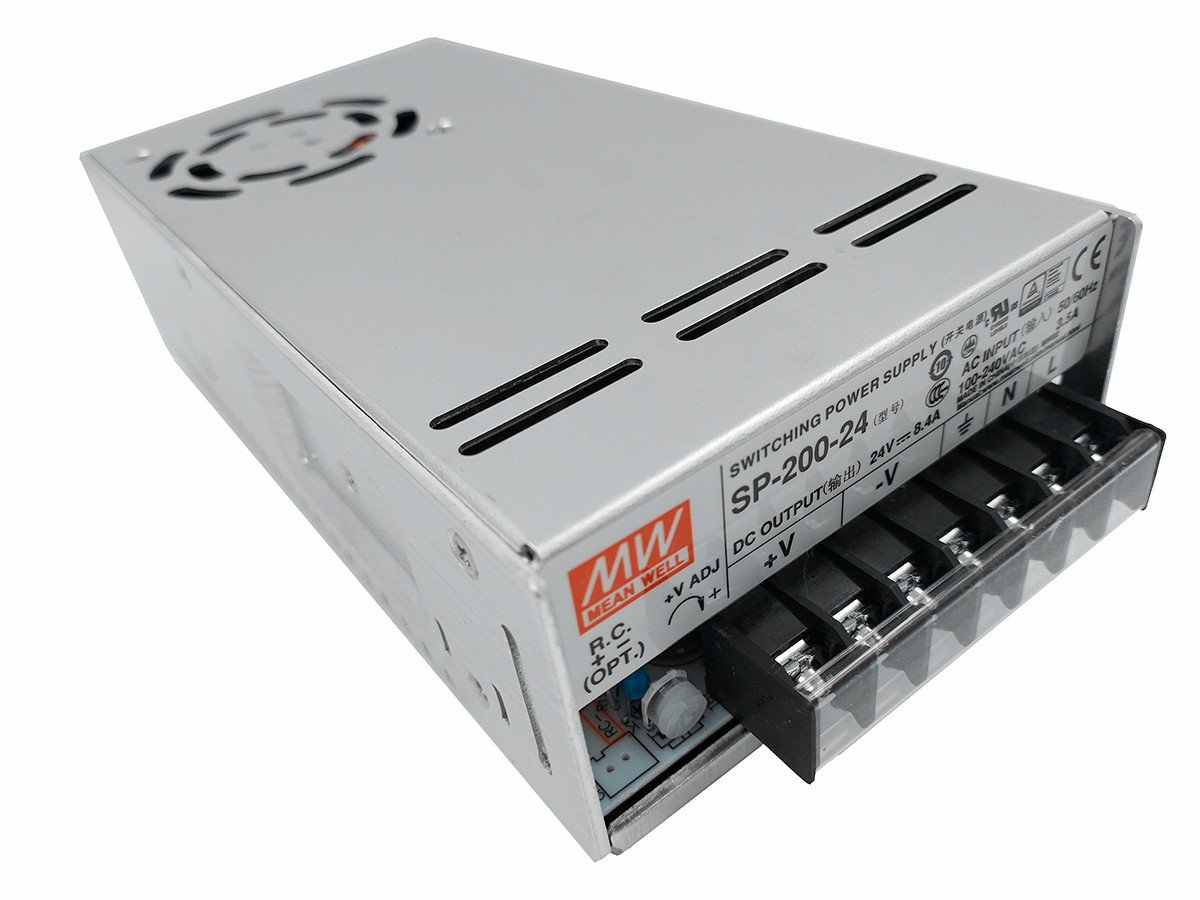
Figure 1: Mechanical Dimensions and Pin Assignments. The unit measures approximately 199mm in length, 99mm in width, and 50mm in height. It features various mounting holes: two M4 holes with 5mm length, five M3 holes with 3mm length, and six M4 holes with 6mm length. Airflow direction is indicated for cooling.
Key dimensions include:
- Overall Dimensions: 199mm (L) x 99mm (W) x 50mm (H).
- Mounting Holes:
- 2 x M4 (L=5mm)
- 5 x M3 (L=3mm)
- 6 x M4 (L=6mm)
- Airflow: Indicated by arrows for proper cooling.
5. Pin Assignment
Refer to Figure 1 for the physical location of the terminals.
5.1. Terminal Pin No. Assignment
| Pin No. | Assignment | Pin No. | Assignment |
|---|---|---|---|
| 1 | AC/L | 4,5 | DC OUTPUT -V |
| 2 | AC/N | 6,7 | DC OUTPUT +V |
| 3 | FG (Frame Ground) |
5.2. Remote ON/OFF (CN1) (Optional)
This feature uses a JST S2B-XH connector or equivalent.
| Pin No. | Assignment | Mating Housing | Terminal |
|---|---|---|---|
| 1 | RC+ | JST XHP or equivalent | JST SXH-001T-P0.6 or equivalent |
| 2 | RC- |
6. Block Diagram
The internal functional blocks of the SP-200-24 power supply are illustrated below, showing the flow of power and control signals.
Figure 2: Functional Block Diagram. The diagram shows the input (I/P) passing through EMI filter & rectifiers, PFC circuit, power switching, and then to rectifiers & filter for DC output. Control loops include PWM & PFC control, constant current limiting & detection, and over voltage protection (O.V.P.). Overload protection (O.L.P.) and over temperature protection (O.T.P.) are also indicated.
Key functional blocks include:
- EMI Filter & Rectifiers: Processes the AC input.
- PFC Circuit: Improves power factor.
- Power Switching: Converts DC to high-frequency AC for efficient transformation.
- Rectifiers & Filter: Converts high-frequency AC back to stable DC output.
- PWM & PFC Control: Regulates output voltage and power factor.
- Protection Circuits: O.L.P. (Overload Protection), O.T.P. (Over Temperature Protection), O.V.P. (Over Voltage Protection), Constant Current Limiting & Detection Circuit.
- Fan Speed Control: Manages the cooling fan operation.
PFC switching frequency (fosc) is 67KHz, and PWM switching frequency (fosc) is 134KHz.
7. Derating Curves
The derating curves illustrate the maximum permissible load under varying environmental conditions. Adhering to these curves ensures optimal performance and longevity of the power supply.
Figure 3: Derating Curves. This image displays two graphs: "Derating Curve" (Load % vs. Ambient Temperature °C) and "Output Derating VS Input Voltage" (Load % vs. Input Voltage VAC). The first graph shows that the power supply can operate at 100% load up to approximately 50°C ambient temperature, after which the load must be reduced. The second graph indicates that the unit can deliver 100% load for input voltages between 100VAC and 264VAC, with a slight derating below 100VAC.
7.1. Derating Curve (Load vs. Ambient Temperature)
This curve shows the maximum output load percentage that can be drawn from the power supply at different ambient temperatures.
- Up to approximately 50°C, the power supply can operate at 100% of its rated load.
- Above 50°C, the output load must be linearly derated to maintain safe operating temperatures.
7.2. Output Derating vs. Input Voltage
This curve illustrates the maximum output load percentage based on the input AC voltage.
- For input voltages between 100VAC and 264VAC, the power supply can deliver 100% of its rated load.
- Below 100VAC (e.g., down to 85VAC), the output load capacity is reduced.
8. Setup and Installation
Follow these steps for proper installation:
- Mounting: Securely mount the power supply using the designated mounting holes (refer to Section 4, Figure 1) in a location that allows for adequate airflow and heat dissipation.
- Input Wiring: Connect the AC mains input to the terminals labeled AC/L (Pin 1) and AC/N (Pin 2). Ensure proper polarity.
- Grounding: Connect the Frame Ground (FG) terminal (Pin 3) to a reliable earth ground. This is critical for safety.
- Output Wiring: Connect your load to the DC OUTPUT -V (Pins 4,5) and DC OUTPUT +V (Pins 6,7) terminals. Observe correct polarity.
- Remote ON/OFF (Optional): If using the remote ON/OFF function, connect the control signals to the CN1 pins (RC+ and RC-) as described in Section 5.2.
- Ventilation: Ensure that the air intake and exhaust vents are not obstructed. Maintain sufficient clearance around the unit for proper cooling.
- Initial Check: Before applying power, double-check all wiring connections for correctness and security.
9. Operating Instructions
Once installed and wired correctly:
- Power On: Apply AC mains power to the unit. The power supply should start operating, and the LED indicator (if present) should illuminate.
- Output Voltage Adjustment: If your model includes a voltage adjustment potentiometer (V ADJ), you can fine-tune the output voltage within a small range. Use a voltmeter to monitor the output during adjustment.
- Monitoring: Periodically check the power supply's temperature and ensure proper ventilation, especially under heavy loads.
- Remote Control: If the remote ON/OFF function is utilized, use the external control signal to switch the power supply on or off.
10. Maintenance
The SP-200-24 power supply is designed for reliable operation with minimal maintenance.
- Cleaning: Periodically inspect the unit for dust accumulation, especially on the cooling fan and vents. Disconnect power before gently cleaning with compressed air or a soft brush.
- Inspection: Check wiring connections for any signs of loosening or damage. Ensure the mounting remains secure.
- No User Serviceable Parts: Do not attempt to open or repair the power supply. Refer all servicing to qualified personnel.
11. Troubleshooting
If the power supply is not functioning as expected, consider the following:
| Problem | Possible Cause | Solution |
|---|---|---|
| No output voltage / Unit not powering on |
|
|
| Output voltage too low or unstable |
|
|
| Unit is excessively hot |
|
|
If troubleshooting steps do not resolve the issue, contact MEAN WELL customer support or a qualified service technician.
12. Specifications
| Parameter | Value |
|---|---|
| Brand | MEAN WELL |
| Model Number | SP-200-24 |
| Output Wattage | 201.6 Watts (200W nominal) |
| Output Voltage | 24V DC |
| Output Current | 8.4A |
| Minimum Input Voltage | 85 Volts AC |
| Maximum Input Voltage | 264 Volts AC |
| Cooling Method | Air (Built-in fan) |
| Item Weight | 2.1 Pounds (approx. 0.95 kg) |
| Dimensions (L x W x H) | 199mm x 99mm x 50mm |
| Compatible Devices | Personal Computer (and other compatible electronic devices) |
13. Warranty and Support
The MEAN WELL SP-200-24 Power Supply is generally covered by a 3-year warranty from the date of purchase. This warranty covers defects in materials and workmanship under normal use.
For technical support, warranty claims, or service inquiries, please contact your authorized MEAN WELL distributor or reseller. Please have your product model number and purchase date available when contacting support.
Note: Any unauthorized modification, improper installation, or operation outside the specified parameters will void the product warranty.


