Introduction
This manual provides essential information for the installation, operation, and maintenance of the Heatilator Old Style Propane (LP) Pilot Assembly, identified by part numbers 25732 and its current equivalent, 4021-729. This assembly is designed for specific Hearth & Home gas stoves and fireplaces that operate without a thermocouple. Please read all instructions carefully before proceeding with installation or service.
Safety Information
WARNING: Improper installation, adjustment, alteration, service, or maintenance can cause injury or property damage. Refer to this manual. For assistance or additional information, consult a qualified installer, service agency, or the gas supplier.
- Gas Safety: Always turn off the gas supply to the appliance before performing any service or maintenance.
- Electrical Safety: Disconnect electrical power to the appliance before installation or service.
- Qualified Personnel: Installation and service must be performed by a qualified service technician.
- Leak Testing: After any gas connection is made, always test for gas leaks using a non-corrosive leak detection solution. Never use an open flame.
- Carbon Monoxide: Ensure proper ventilation and regularly check for carbon monoxide leaks. Carbon monoxide is an odorless, colorless gas that can cause serious injury or death.
- Original Parts: Use only genuine replacement parts as specified by the manufacturer.
Package Contents
Verify that all components are present and undamaged before beginning installation.
- 1 x Heatilator Old Style Propane Pilot Assembly (Part #25732 / #4021-729)

Figure 1: Complete Heatilator Old Style Propane Pilot Assembly, showing the pilot burner, igniter, gas line, and electrical connections.
Compatibility
This pilot assembly (HHT part #4021-729, replacing old part #25732) is a replacement propane (LP) pilot assembly for Hearth & Home gas stoves and fireplaces that do not utilize a thermocouple. It is compatible with the following HHT gas fireplace models. Always verify compatibility with your appliance's owner's manual.
Quadra-Fire Gas Stoves:
- DV400 & DV400L (Pre date code 12/96)
Heatilator Gas Fireplaces:
- EZ & EZL
- G112HA & G112HAL
- G360S & G360SL
- G520CL & G520CLL
- G520CR & G520CRL
- G760CH & G760CHL
- G920FL & G920FLL
- GC112 & GC112L
- GC300FL & GC300FLL (Pre date code 21/96)
- GC300ST & GC300STL (Pre date code 21/96)
- GC400SF & GC400SFL (Pre date code 21/96)
- GC500CL & GC500CLL (Pre date code 21/96)
- GC500CR & GC500CRL (Pre date code 21/96)
- GC720 & GC720L
- GC920 & GC920L
- CGC150 & CGC150L (Pre date code 39/95)
- CGC400 & CGC400L
- G136 & G136L
- G200 & G200L
- G340 & G340L
- G420 & G420L
- GC100A & GC100AL
- GC136 & GC136L
- GC150 & GC150L (Pre date code 39/95)
- GC200 & GC200L
- GC300 & GC300L
- GC340 & GC340L
- GC341 & GC341L
- GC341A & GC341AL
- GC361 & GC361L
- GC400 & GC400L
- GC420 & GC420L
- GC421 & GC421L
- GC1990 & GC1990L
- GC2000 & GC2000L
- GGBC36 & GGBC36L
- GGBC42 & GGBC42L
- GGBR36 & GGBR36L
- GGBR42 & GGBR42L
- DLS2 & DLS2L
- DLS18 & DLS18L
- DLS24 & DLS24L
- DLS30 & DLS30L
- FD36M & FD36ML
- FD42M & FD42ML
Installation Instructions
This procedure should only be performed by a qualified service technician.
- Preparation:
- Turn off the gas supply to the appliance at the main shut-off valve.
- Disconnect electrical power to the appliance.
- Allow the appliance to cool completely if it has been in operation.
- Access the pilot assembly area within your fireplace or stove, typically by removing the log set, burner, or access panels.
- Removal of Old Pilot Assembly:
- Carefully disconnect the gas line from the old pilot assembly. Be prepared for a small amount of residual gas.
- Disconnect any electrical wires (e.g., igniter wire) from the old assembly. Note their connections for reinstallation.
- Unscrew or unclip the mounting bracket that secures the old pilot assembly to the burner or firebox.
- Remove the old pilot assembly from the appliance.
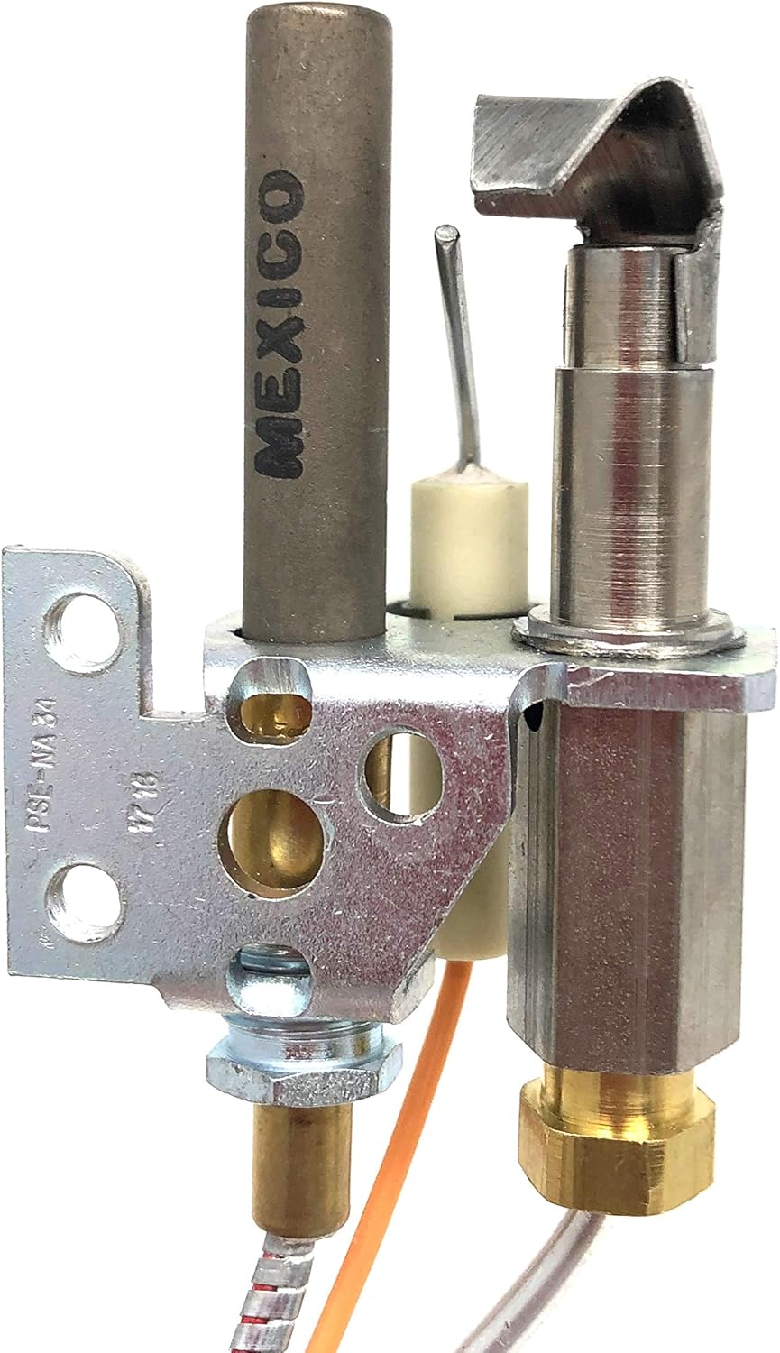
Figure 2: Close-up view of the pilot assembly, highlighting the pilot burner, igniter, and mounting bracket with screw holes.
- Installation of New Pilot Assembly:
- Position the new pilot assembly in the same location as the old one.
- Secure the pilot assembly using its mounting bracket and appropriate screws. Ensure it is firmly in place and correctly oriented.
- Connect the gas line to the new pilot assembly. Use a pipe thread sealant approved for gas connections. Tighten securely but do not overtighten.
- Connect the electrical wires (e.g., igniter wire) to the corresponding terminals on the new pilot assembly. Refer to your appliance's wiring diagram if unsure.

Figure 3: Detailed view of the pilot assembly's igniter electrode and the gas inlet connection point.
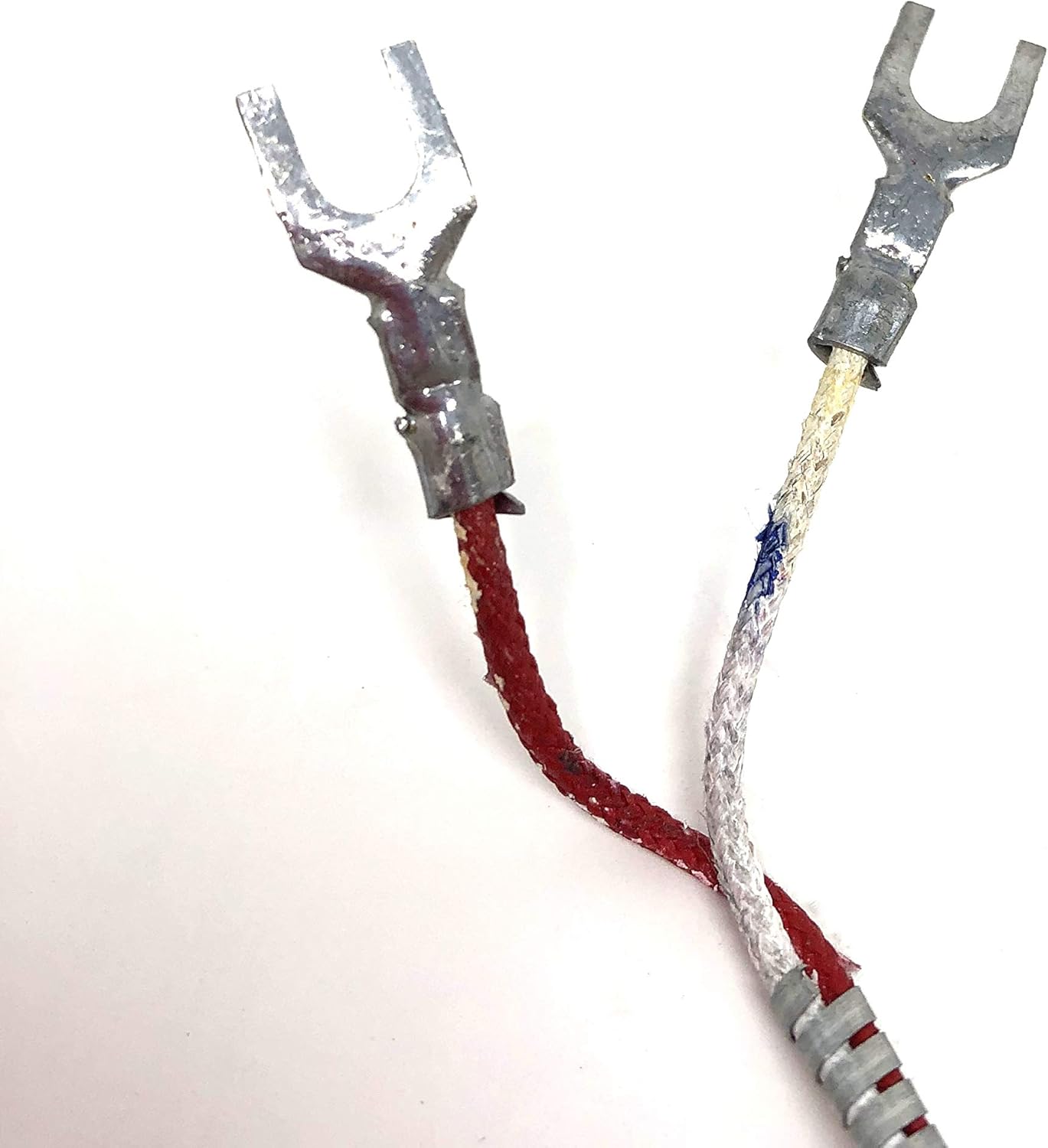
Figure 4: Electrical spade connectors used for wiring the pilot assembly, ensuring a secure connection.
- Leak Testing:
- Slowly turn on the main gas supply to the appliance.
- Apply a non-corrosive leak detection solution to all gas connections made during installation.
- Look for bubbles, which indicate a gas leak. If bubbles are present, turn off the gas supply immediately, tighten the connection, and retest. Repeat until no leaks are detected.
- Testing Operation:
- Restore electrical power to the appliance.
- Follow your appliance's specific instructions to light the pilot.
- Observe the pilot flame. It should be steady, blue, and impinge correctly on the main burner port to ensure proper ignition.
- If the pilot does not light or stay lit, refer to the Troubleshooting section.
Operation Overview
The pilot assembly serves as a continuous ignition source for your gas fireplace or stove. When the appliance is called to heat, the pilot flame ignites the main burner. This specific pilot assembly operates without a thermocouple, relying on other safety mechanisms within your appliance to monitor pilot flame presence.
Maintenance
Regular inspection and cleaning can prolong the life and ensure the safe operation of your pilot assembly. Perform these checks annually or as recommended by your appliance's manufacturer.
- Visual Inspection: Check the pilot flame for proper size and color (should be blue with a small yellow tip). Ensure it is directed correctly towards the main burner.
- Cleaning: Gently clean any dust, lint, or debris from the pilot burner and igniter electrode using a soft brush or compressed air. Ensure the pilot orifice is clear.
- Connections: Inspect all gas and electrical connections for tightness and signs of wear or corrosion.
Troubleshooting
If you experience issues with your pilot assembly, consult this section. For persistent problems, contact a qualified service technician.
| Problem | Possible Cause | Solution |
|---|---|---|
| Pilot will not light |
|
|
| Pilot lights but goes out |
|
|
| Weak or yellow pilot flame |
|
|
Specifications
| Part Numbers | 25732 (Old Style), 4021-729 (Current) |
| Fuel Type | Propane (LP) |
| Thermocouple | Not included / For units without a thermocouple |
| Manufacturer | HHT (Heat & Glo / Heatilator) |
| Item Weight | 4.9 ounces |
| Package Dimensions | 7.76 x 5.75 x 2.05 inches |
| ASIN | B00MPXSMT6 |
| Item Model Number (Internal) | 8541800512 |
| Batteries Required | No |
Warranty and Support
For warranty information or technical support regarding your Heatilator Old Style Propane Pilot Assembly, please refer to the documentation provided with your specific Hearth & Home appliance or contact the manufacturer directly. Always ensure that any service or replacement is performed by a qualified professional.