
1. Introduction
The Tekpower TP8260L is a versatile 20-range analog multimeter designed for various electrical measurements. It allows users to accurately measure AC/DC voltage, DC current, resistance, continuity, decibel values (dB), and perform diode and transistor tests.
Key features of this multimeter include:
- High accuracy for AC and DC voltage, and DC current up to 10A.
- Integrated backlight for improved visibility in low-light conditions.
- Decibel value measurement capability.
- Zero adjustment function for resistance measurements.
- Transistor checker for both PNP and NPN types with an LED indicator.
- Compliance with EN61010/IEC1010 standard CAT II 600V.
- Robust protective case for durability.
2. Safety Information
Please read and understand all safety instructions before operating the Tekpower TP8260L Analog Multimeter. Failure to follow these instructions may result in electric shock, fire, or damage to the meter or the equipment under test.
- Always ensure the multimeter is set to the correct range and function before connecting test leads to a circuit.
- Do not attempt to measure voltages or currents exceeding the maximum rated values for each range. The meter is rated for CAT II 600V.
- Exercise extreme caution when working with live electrical circuits. Avoid contact with bare wires or terminals.
- Inspect test leads for damage (cracks, frayed insulation) before each use. Replace damaged leads immediately.
- Do not operate the meter if it appears damaged or if the case is open.
- Remove test leads from the circuit before changing functions or ranges.
- When measuring resistance or continuity, ensure the circuit is de-energized and all capacitors are discharged.
- Replace batteries promptly when the low battery indicator appears to ensure accurate readings.
3. Product Overview
Familiarize yourself with the components of your Tekpower TP8260L Analog Multimeter.

Figure 1: Front view of the Tekpower TP8260L Analog Multimeter with its illuminated display.
The multimeter features a large analog display for clear readings, a central rotary switch for function and range selection, and various input jacks for test leads. A dedicated transistor checking dock is also present.
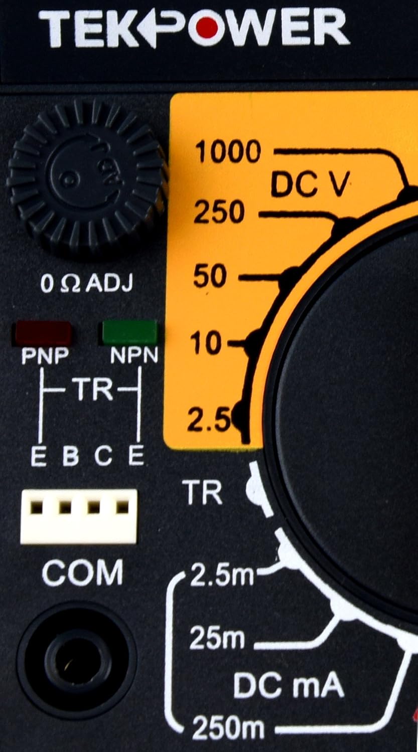
Figure 2: Close-up of the transistor test dock (TR) and DC Voltage (DCV) selection area.
- Analog Display: Shows measurement values via a needle against various scales.
- Rotary Switch: Selects the desired measurement function (DCV, ACV, DCA, Ohm) and range.
- Input Jacks: Connect test leads. Typically, 'COM' for common (negative) and 'V.Ω.A' for positive input. A separate 'DC 10A' jack is for high current measurements.
- 0 Ω ADJ Knob: Used to zero the needle for resistance measurements.
- TR (Transistor) Dock: For testing PNP and NPN transistors.
- Light Button: Activates the display backlight.
4. Setup
4.1 Package Contents
Verify that your package contains the following items:
- Tekpower TP8260L Analog Multimeter
- Test leads with shrouded plugs and capped tips
- User Manual

Figure 3: Contents of the Tekpower TP8260L package, including the multimeter, test leads, and manual.
4.2 Battery Installation
The TP8260L requires two (2) AA batteries and one (1) 9V battery for operation. To install or replace batteries:
- Ensure the multimeter is turned OFF and disconnect all test leads.
- Locate the battery compartment cover on the back of the meter.
- Unscrew the retaining screw(s) and carefully remove the cover.
- Insert the AA and 9V batteries, observing the correct polarity (+/-) as indicated inside the compartment.
- Replace the battery compartment cover and secure it with the screw(s).
4.3 Connecting Test Leads
For most measurements (voltage, resistance, low current):
- Insert the black test lead into the COM (Common) jack.
- Insert the red test lead into the V.Ω.A jack.
For high DC current measurements (up to 10A):
- Insert the black test lead into the COM jack.
- Insert the red test lead into the DC 10A jack.

Figure 4: The multimeter with its test leads properly connected to the COM and V.Ω.A jacks.
5. Operating Instructions
Always select the appropriate function and range before making a measurement. If the measurement value is unknown, start with the highest range and work downwards until a suitable reading is obtained.
5.1 DC Voltage Measurement (DCV)
- Set the rotary switch to the desired DCV range (2.5V, 10V, 50V, 250V, 1000V).
- Connect the black test lead to the negative (-) side of the circuit and the red test lead to the positive (+) side.
- Read the DCV value from the corresponding scale on the analog display.
5.2 AC Voltage Measurement (ACV)
- Set the rotary switch to the desired ACV range (10V, 50V, 250V, 500V, 1000V).
- Connect the test leads across the AC voltage source. Polarity is not critical for AC measurements.
- Read the ACV value from the corresponding scale on the analog display.
5.3 DC Current Measurement (DCA)
Caution: Always connect the multimeter in series with the circuit when measuring current. Never connect it in parallel across a voltage source, as this can damage the meter and blow fuses.
- Set the rotary switch to the desired DCA range (2.5mA, 25mA, 250mA, 10A).
- For 10A measurements, ensure the red test lead is in the DC 10A jack. For other ranges, use the V.Ω.A jack.
- Open the circuit where current is to be measured and connect the multimeter in series.
- Read the DCA value from the corresponding scale.
5.4 Resistance Measurement (Ohms)
Caution: Ensure the circuit is de-energized before measuring resistance.
- Set the rotary switch to the desired Ohm range (x1, x10, x1K, x10K).
- Short the red and black test leads together.
- Adjust the 0 Ω ADJ knob until the needle points exactly to '0' on the Ohms scale.
- Connect the test leads across the component whose resistance is to be measured.
- Read the value from the Ohms scale and multiply by the selected range multiplier (e.g., if reading is 50 on x10 range, resistance is 500 Ohms).
5.5 Continuity Test
The continuity function typically shares a range with resistance. When continuity is detected, the meter will emit an audible beep.
- Set the rotary switch to the continuity/resistance range, usually indicated by a buzzer symbol.
- Connect the test leads across the component or circuit path.
- An audible beep indicates a continuous path (low resistance).
5.6 Decibel Value Measurement (dB)
The dB scale is often integrated with AC voltage ranges. Refer to the specific dB scale on the meter face for readings.
- Set the rotary switch to an appropriate ACV range that also has a dB scale.
- Connect the test leads across the AC signal source.
- Read the decibel value from the dB scale.
5.7 Diode Test
The diode test function uses a resistance range to check diode functionality.
- Set the rotary switch to a resistance range, typically x1 or x10.
- Connect the red test lead to the anode and the black test lead to the cathode of the diode. The meter should show a low resistance reading (forward bias).
- Reverse the test leads. The meter should show a very high or infinite resistance reading (reverse bias).
- If both readings are low or both are high, the diode may be faulty.
5.8 Transistor Checking (TR)
The transistor dock allows for basic testing of PNP and NPN transistors.
- Identify the transistor type (PNP or NPN) and its emitter (E), base (B), and collector (C) leads.
- Set the rotary switch to the 'TR' position.
- Insert the transistor leads into the corresponding E, B, C slots in the PNP or NPN section of the transistor dock.
- Observe the LED indicator. A successful test typically illuminates the LED, indicating the transistor is functional and correctly inserted.
5.9 Backlight Operation
Press the 'light' button to illuminate the display for better visibility in dark environments. The backlight will typically stay on for a short period before automatically turning off to conserve battery life.
6. Maintenance
6.1 Cleaning
Wipe the meter's case with a damp cloth and a mild detergent. Do not use abrasives or solvents. Ensure the meter is dry before use.
6.2 Battery Replacement
Refer to Section 4.2 for detailed instructions on replacing the AA and 9V batteries. Replace batteries when the display becomes dim or readings become erratic.
6.3 Fuse Replacement
The TP8260L is protected by two fuses: a 250 mA / 250 V fuse and a 10 A / 250 V fuse. If the meter fails to measure current or resistance, a fuse may be blown.
- Ensure the multimeter is turned OFF and disconnect all test leads.
- Open the back case of the meter (this may require unscrewing multiple screws).
- Locate the blown fuse(s).
- Replace with fuses of the exact same type and rating (250 mA / 250 V and 10 A / 250 V). Never use a fuse with a different rating.
- Carefully reassemble the meter, ensuring all screws are tightened.
6.4 Storage
If the meter is not to be used for an extended period, remove the batteries to prevent leakage and store it in a cool, dry place away from direct sunlight.
7. Troubleshooting
If your Tekpower TP8260L is not functioning as expected, refer to the following common issues and solutions:
- No display or dim display: Check battery levels. Replace AA and 9V batteries if necessary.
- No reading for current or resistance: Check the fuses (250 mA / 250 V and 10 A / 250 V). Replace if blown. Ensure test leads are correctly connected and the rotary switch is on the correct range.
- Inaccurate resistance readings: Perform a zero adjustment using the 0 Ω ADJ knob before measurement. Ensure the circuit is de-energized.
- Backlight not working: Check battery levels. The backlight has a timed auto-off feature.
- No continuity beep: Ensure the meter is set to the continuity range. Check test leads for proper connection and integrity.
If problems persist after attempting these troubleshooting steps, contact customer support.
8. Technical Specifications
| Parameter | Specification |
|---|---|
| Power Source | 2 x AA Batteries, 1 x 9V Battery |
| Battery Life | Approximately 10 hours of continuous use |
| Dimensions (L x W x H) | 15.88 x 10.16 x 3.18 cm (6.5" x 3.5" x 1.5") |
| Weight | 396 g (14.3 Oz) |
| Fuses | 250 mA / 250 V, 10 A / 250 V |
| DC Voltage (DCV) Ranges | 0 - 2.5V, 10V, 50V, 250V, 1000V (Accuracy: ±3.0%) |
| AC Voltage (ACV) Ranges | 0 - 10V, 50V, 250V, 500V, 1000V (Accuracy: ±4.0%) |
| DC Current (DCA) Ranges | 2.5 mA, 25 mA, 250 mA, 10A (Accuracy: ±4.0%, all ranges fused) |
| Resistance Ranges | 1-2KΩ (x1), 20KΩ (x10), 2MΩ (x1K), 20MΩ (x10K) (Accuracy: ±3.0%) |
| Other Functions | Continuity, Decibel Value, Diode Test, Transistor Test (PNP/NPN) |
| Safety Standard | EN61010/IEC1010 CAT II 600V |
| Input Impedance | 20KΩ/V DC, 8KΩ/V AC |
9. Warranty and Support
The Tekpower TP8260L Analog Multimeter comes with a 1-year warranty from the date of purchase, covering defects in materials and workmanship.
For warranty claims, technical support, or service inquiries, please refer to the contact information provided with your purchase documentation or visit the official Tekpower website. Please have your model number (TP8260L) and proof of purchase ready when contacting support.