1. Product Overview
The HeatTech Electric Floor Heating Cable Kit provides radiant floor heating for various floor types and spaces. This system is designed for installation under tile, stone, granite, marble, and other compatible floor coverings in areas such as bathrooms, kitchens, showers, and saunas. It is suitable for both new construction and retrofit projects in residential settings.
The kit includes a 120V electric radiant heating cable, a 7-day programmable Aube TH115-AF-120S thermostat with a floor sensor, cable guides, and detailed installation instructions. The heating cable is approximately 1/8 inch thick, ensuring minimal floor height increase, and features zero electromagnetic field (EMF) emission. It comes with a single armored 10-foot long cold lead wire for direct connection to the thermostat.

Image 1.1: Components of the HeatTech Electric Floor Heating Cable Kit, showing the heating cable spool, Aube thermostat, floor sensor, and cable guides.
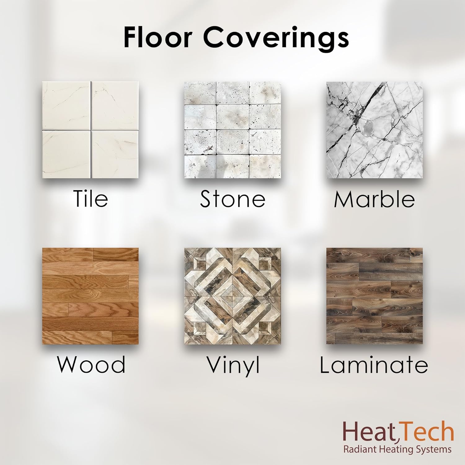
Image 1.2: Compatible floor coverings for the HeatTech system, including tile, stone, marble, wood, vinyl, and laminate.
2. Safety Information
Important: Read all instructions carefully before installation and operation. Failure to follow these instructions may result in electric shock, fire, or property damage.
- Installation must be performed by a qualified electrician in accordance with local and national electrical codes.
- Ensure power is disconnected at the main circuit breaker before performing any electrical work.
- The heating cable must never be cut or shortened. Doing so will alter its resistance and may cause overheating or system failure.
- Do not install heating cable under permanent fixtures that do not allow for an air gap of at least 4 inches underneath (e.g., cabinets without legs, bathtubs without an air gap).
- Always perform resistance and insulation tests before, during, and after installation to verify cable integrity.
- The heating cable must be fully embedded in thinset mortar or self-leveling cement.
- Do not energize the system until the underlayment and thinset have fully cured, typically 7-28 days depending on the product used.
- Keep the cold lead wire and floor sensor away from sharp objects and potential damage during installation.
3. Installation Guide
3.1 Pre-Installation Planning and Measurement
Accurate measurement of your heated area is crucial for selecting the correct cable size. The heating cable cannot be cut or shortened. Always select a cable size that is equal to or slightly less than your calculated heated area.
- Mark out fixtures: Identify and mark all permanent fixtures (e.g., cabinets, toilets, bathtubs) that will not have an air gap of at least 4 inches underneath. The heating cable should not be installed under these areas.
- Mark out perimeter spacing: Measure and mark a 3-inch perimeter from all walls and permanent fixtures. The heating cable should not be installed within this perimeter.
- Measure the heated area: Calculate the total square footage of the area where the heating cable will be installed, excluding the marked-out fixtures and perimeter.
Video 3.1: This video demonstrates the process of measuring your floor area to determine the correct size for your heated floor system, including marking out fixtures and perimeter spacing.
3.2 Subfloor Preparation and Membrane Installation
- Ensure the subfloor is clean, dry, and structurally sound.
- Lay out the uncoupling membrane over the prepared subfloor. Cut the membrane into sections as needed to cover your desired heating area.
- Apply thinset mortar to the subfloor using a notched trowel. Firmly press the uncoupling membrane sections into the thinset, ensuring a strong bond to the subfloor.
- Allow the thinset to cure according to the manufacturer's instructions before proceeding.
Video 3.2: This video provides a step-by-step guide on installing the LuxHeat floor heating cable with a Prova membrane, covering membrane layout, thinset application, and cable lacing.
3.3 Heating Cable and Sensor Installation
- Initial Cable Test: Before laying the cable, perform a resistance test on the heating cable using a multimeter. Record the reading in your test log.
- Connect Installation Monitor: Connect an installation monitor (if available) to the heating cable's cold lead wires. This device will alert you to any damage during installation.
- Lace the Heating Cable: Carefully lace the heating cable into the channels of the uncoupling membrane. Maintain a consistent spacing of 3 inches between runs for optimal heat output. Ensure the cable does not cross over itself or come into contact with other cables. The cable must not be cut or shortened.
- Install Floor Sensor: Install the floor sensor in a channel between two heating cable runs, ensuring it is centered and not touching the heating cable. The sensor should be placed in a representative heated area, away from direct sunlight or drafts.
- Second Cable Test: After the cable and sensor are fully laid out but before covering them, perform another resistance test on the heating cable and the floor sensor. Record these readings.
3.4 Covering the Heating System and Final Flooring
- Apply Underlayment: Apply a layer of thinset mortar or self-leveling cement over the heating cable and membrane, ensuring all cables are completely covered and encapsulated. This layer protects the cable and provides a flat surface for your final flooring.
- Install Floor Covering: Once the underlayment has cured (refer to product specifications for curing times), apply thinset and install your chosen floor covering (tile, stone, etc.) according to the flooring manufacturer's instructions.
- Final Cable Test: After the final floor covering is installed and the thinset has cured, perform a final resistance test on the heating cable and floor sensor. Record these readings in your test log.

Image 3.1: Framed floor construction and applications, showing heating cable embedded in thin-set mortar over a plywood subfloor.
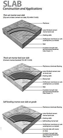
Image 3.2: Slab construction and applications, showing heating cable embedded in thin-set mortar over a concrete slab.
3.5 Thermostat Installation
The Aube TH115-AF-120S thermostat is included in your kit. Refer to the separate instruction manual provided with the thermostat for detailed wiring and installation procedures. Ensure all electrical connections are made by a qualified electrician.
Crucial Note: Do not energize the heating system until the underlayment and final floor covering's thinset have fully cured. This typically requires a minimum of 7 days, but can be up to 28 days depending on environmental conditions and materials used. Refer to the thinset/mortar manufacturer's guidelines for specific curing times.

Image 3.3: The Aube TH115-AF-120S thermostat kit, showing the thermostat, floor sensor, and accompanying documentation.
4. Operating Instructions (Aube TH115-AF-120S Thermostat)
Your HeatTech system is controlled by the Aube TH115-AF-120S 7-day programmable thermostat. This thermostat offers precise temperature control and scheduling capabilities.
- Programmable Schedule: The thermostat allows for a 7-day programmable schedule with up to 4 time periods per day, enabling energy-efficient heating tailored to your lifestyle.
- Adjustable Temperature: Temperature can be adjusted between 60°F and 104°F (15°C - 40°C).
- Temperature Control Modes: The thermostat offers three control options:
- Ambient: Controls room air temperature.
- Floor: Controls floor temperature using the floor sensor.
- Ambient with Floor Limit: Controls room air temperature while preventing the floor from exceeding a set maximum temperature.
- Special Features: Includes quiet operation, temperature display, and a vacation mode for energy savings when away.
For detailed programming and operation instructions, please consult the dedicated Aube TH115-AF-120S thermostat user manual.

Image 4.1: Aube TH115-AF-120S programmable thermostat interface.
5. Maintenance
The HeatTech Electric Floor Heating System is designed for maintenance-free operation once properly installed. However, consider the following:
- Cleaning: Clean the thermostat display and buttons with a soft, dry cloth. Avoid abrasive cleaners or solvents.
- System Checks: If you suspect a malfunction, consult the troubleshooting section or a qualified electrician. Do not attempt to repair the heating cable or thermostat yourself.
- Floor Integrity: Ensure the integrity of your floor covering. Any damage to the floor that could expose or damage the heating cable should be addressed promptly by a professional.
6. Troubleshooting
If your HeatTech Electric Floor Heating System is not operating as expected, consider the following common issues:
- No Heat:
- Check the circuit breaker: Ensure the circuit breaker supplying power to the thermostat is not tripped.
- Thermostat settings: Verify the thermostat is set to a heating mode and the desired temperature is above the current floor/ambient temperature.
- GFCI trip: If the thermostat has a built-in GFCI or is connected to an external GFCI, check if it has tripped. Reset if necessary.
- Uneven Heating:
- Cable spacing: Uneven heating can result from inconsistent cable spacing during installation. This cannot be corrected after installation.
- Floor sensor placement: Ensure the floor sensor is correctly placed between two cable runs and not directly over a cable or in an unheated area.
- Thermostat Display Issues:
- Power supply: Check the power supply to the thermostat.
- Error codes: Refer to the Aube TH115-AF-120S manual for specific error codes and their meanings.
For issues not resolved by these steps, or if you suspect damage to the heating cable, contact a qualified electrician or HeatTech customer support.
7. Specifications
| Feature | Specification |
|---|---|
| Brand | HeatTech |
| Model Name | HTCBL-KIT-120V-400ft |
| Heated Area Coverage | 100 sq.ft. (at 3" spacing) |
| Heating Cable Length | 400 ft |
| Voltage | 120 Volts |
| Wattage | 1200 watts |
| Amperage | 10 Amps |
| Cable Thickness | ~1/8 inch |
| EMF | Zero EMF |
| Cold Lead Wire Length | 10 ft (armored) |
| Thermostat Model | Aube TH115-AF-120S |
| Thermostat Features | 7-day Programmable, Adjustable Temperature (60F-104F), Quiet Operation, Temperature Display, Vacation Mode, Ambient/Floor/Ambient with Floor Limit control |
| Floor Sensor Length | 15 ft |
| Certifications | UL listed and/or ETL listed for USA and Canada |
| Material | Electric floor heating cable must be fully embedded in thinset or self-leveling cement |
| Item Weight | 9 Pounds |
| Product Dimensions | 6 x 9 x 12 inches (packaging) |
8. Warranty and Support
HeatTech stands behind the quality of its products:
- Electric Floor Heating Cable: Comes with a 25-year Warranty.
- AUBE Thermostats: Covered by a 3-year Manufacturer's Warranty.
For warranty claims, technical support, or further assistance, please contact HeatTech customer service. Keep your proof of purchase and installation records handy.


