1. Introduction
Thank you for choosing the Mastech MS2115B True RMS Digital Clamp Meter. This instrument is designed for safe and accurate measurement of various electrical parameters. This manual provides essential information for the proper and safe operation, maintenance, and troubleshooting of your device. Please read this manual thoroughly before use and retain it for future reference.
2. Safety Information
To ensure safe operation and service of the meter, follow these safety precautions:
- Always adhere to local and national safety codes.
- Do not use the meter if it appears damaged or if the insulation on the test leads is compromised.
- Never apply more than the rated voltage, as marked on the meter, between terminals or between any terminal and ground.
- Use extreme caution when working with voltages above 60V DC or 30V AC RMS. These voltages pose a shock hazard.
- Keep your fingers behind the probe barriers when making measurements.
- Disconnect the test leads from the circuit before changing functions.
- Remove the test leads from the meter before opening the battery cover.
- Replace the battery as soon as the low battery indicator appears to avoid incorrect readings.
- Do not operate the meter in explosive gas, vapor, or dust environments.
- Ensure the clamp jaw is fully closed when taking current measurements.
3. Product Overview
The Mastech MS2115B is a True RMS digital clamp meter designed for professional and home use. It offers a wide range of measurement capabilities and features for electrical testing.
3.1 Key Features
- Dual Display with 6000 counts for clear readings.
- Jaw size up to Ø40mm (1.6 inch) for various conductor sizes.
- Auto Ranging and Manual Ranging capabilities.
- DC/AC current measurement up to 1000A.
- Tests AC/DC voltage and current, resistance, capacitance, frequency, and duty cycle.
- True RMS (Root Mean Square) measurement for accurate readings on non-sinusoidal waveforms.
- NCV (Non-Contact Voltage Detector) for identifying live wires without direct contact.
- Inrush current measurement for motor startup analysis.
- Data Hold, MAX/MIN Value Measurement, and Relative Measurement functions.
- Diode test and Continuity Buzzer (<50 ohm).
- Display Backlight and Work Light for use in dimly lit areas.
- Low Battery Display and Auto Power Off for extended battery life.
- USB interface for data communication with Windows OS.
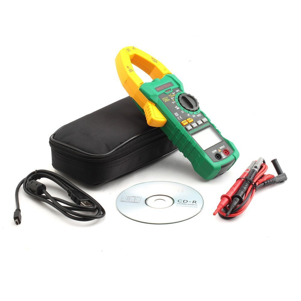
3.2 Components
Familiarize yourself with the main components of the MS2115B clamp meter:


4. Setup
4.1 Battery Installation
The Mastech MS2115B requires batteries for operation. Please note that batteries are not included in the package.
- Ensure the meter is turned OFF and disconnect all test leads.
- Locate the battery compartment cover on the back of the meter.
- Use a screwdriver to loosen the screw securing the battery cover.
- Carefully remove the battery cover.
- Insert the required batteries, observing correct polarity (+ and -).
- Replace the battery cover and secure it with the screw.

4.2 Connecting Test Leads
For voltage, resistance, capacitance, frequency, diode, and continuity measurements, connect the test leads:
- Insert the red test lead into the "INPUT" terminal.
- Insert the black test lead into the "COM" (common) terminal.
4.3 USB Interface Setup (for Windows OS)
The MS2115B features a USB interface for data logging and analysis on a computer running Windows OS.
- Install the provided communication software from the included CD onto your Windows computer.
- Connect the USB communication cable to the meter's USB port and to an available USB port on your computer.
- Follow the software instructions to establish communication and begin data transfer.
5. Operating Instructions
5.1 Power On/Off and Auto Power Off
- To power on, rotate the rotary switch from "OFF" to any desired measurement function.
- To power off, rotate the rotary switch back to "OFF".
- The meter features an Auto Power Off function to conserve battery life. It will automatically turn off after approximately 15 minutes of inactivity. To disable this feature temporarily, refer to the full user manual for specific button combinations during power-on.
5.2 Function Buttons
- FUNC: Selects between different measurement modes within a single rotary switch position (e.g., AC/DC voltage, Diode/Continuity).
- RANGE: Toggles between auto-ranging and manual ranging. In manual ranging, press repeatedly to cycle through ranges.
- HOLD: Freezes the current display reading. Press again to release.
- MAX/MIN: Displays the maximum or minimum reading recorded since activation. Press repeatedly to cycle through MAX, MIN, and current readings.
- REL/ZERO: Activates relative measurement mode, displaying the difference between the current reading and a stored reference value. Also used for zeroing DC current readings.
- INRUSH: Measures the inrush current (startup current) of motors or other inductive loads.
- Backlight/Work Light: Activates the display backlight and work light for improved visibility.
5.3 Measurement Procedures
5.3.1 DC/AC Voltage Measurement
- Connect the red test lead to the "INPUT" terminal and the black test lead to the "COM" terminal.
- Rotate the rotary switch to the V (Voltage) position. Press FUNC to select between DC V= or AC V~.
- Touch the test probes to the desired test points in the circuit.
- Read the voltage value on the display.
5.3.2 DC/AC Current Measurement (Clamp)
- Rotate the rotary switch to the A (Current) position. Press FUNC to select between DC A= or AC A~.
- Open the clamp jaw and enclose only one conductor of the circuit. Ensure the jaw is fully closed.
- For DC current, press REL/ZERO to zero the display before measurement if needed.
- Read the current value on the display.
5.3.3 Resistance Measurement
- Connect test leads as for voltage.
- Rotate the rotary switch to the Ω (Resistance) position.
- Ensure the circuit under test is de-energized.
- Touch the test probes across the component or circuit to measure resistance.
- Read the resistance value on the display.
5.3.4 Capacitance Measurement
- Connect test leads as for voltage.
- Rotate the rotary switch to the CAP (Capacitance) position.
- Ensure the capacitor is fully discharged before measurement.
- Touch the test probes across the capacitor terminals.
- Read the capacitance value on the display.
5.3.5 Frequency and Duty Cycle Measurement
- Connect test leads as for voltage.
- Rotate the rotary switch to the Hz/% (Frequency/Duty Cycle) position.
- Press FUNC to toggle between Frequency (Hz) and Duty Cycle (%).
- Touch the test probes to the signal source.
- Read the frequency or duty cycle value on the display.
5.3.6 Diode Test and Continuity
- Connect test leads as for voltage.
- Rotate the rotary switch to the Diode/Continuity position.
- Press FUNC to select between Diode test or Continuity test.
- For Diode Test: Touch the red probe to the anode and the black probe to the cathode. The display shows the forward voltage drop. Reverse the probes to check for open circuit.
- For Continuity Test: Touch the probes to the circuit. A continuous beep indicates continuity (resistance less than 50 ohms).
5.3.7 NCV (Non-Contact Voltage) Detection
- Rotate the rotary switch to the NCV position.
- Move the top of the clamp meter near a conductor or outlet.
- The meter will emit an audible beep and the NCV indicator will light up if AC voltage is detected.
5.3.8 Inrush Current Measurement
- Rotate the rotary switch to the A~ (AC Current) position.
- Press the INRUSH button.
- Open the clamp jaw and enclose only one conductor of the circuit where the inrush current is to be measured.
- Turn on the device or motor. The meter will capture and display the peak inrush current.
6. Maintenance
6.1 Cleaning
- Periodically wipe the case with a damp cloth and mild detergent. Do not use abrasives or solvents.
- Keep the input terminals free of dirt and moisture.
6.2 Battery Replacement
When the low battery indicator appears on the display, replace the batteries immediately to ensure accurate readings. Refer to Section 4.1 for battery installation instructions.
6.3 Storage
- If the meter is not used for an extended period, remove the batteries to prevent leakage and damage.
- Store the meter in a cool, dry place, away from direct sunlight and extreme temperatures.
7. Troubleshooting
If you encounter issues with your Mastech MS2115B, refer to the following common troubleshooting steps:
| Problem | Possible Cause | Solution |
|---|---|---|
| Meter does not power on. | Dead or incorrectly installed batteries. | Check battery polarity; replace batteries. |
| No reading or "OL" displayed. | Open circuit, out of range, or incorrect function selected. | Check circuit connections, select appropriate range/function, ensure continuity. |
| Inaccurate readings. | Low battery, dirty test leads/terminals, external interference. | Replace batteries, clean leads/terminals, move away from strong electromagnetic fields. |
| Auto Power Off activates too quickly. | Normal operation (15 min inactivity). | Press any button or rotate the switch to reset the timer. Refer to the full manual to disable this feature if needed. |
| Clamp current reading is zero or incorrect. | Multiple conductors in jaw, jaw not fully closed, DC current not zeroed. | Ensure only one conductor is in the jaw, close jaw completely, press REL/ZERO for DC current. |
If the problem persists after trying these steps, please contact Mastech customer support or your local distributor for assistance.
8. Technical Specifications
The following table outlines the technical specifications for the Mastech MS2115B Digital Clamp Meter:
| Measurement Function | Range | Accuracy |
|---|---|---|
| DC Voltage | 600mV / 6V / 60V / 600V / 1000V | ±(0.5% + 3) for 600mV-600V, ±(0.8% + 2) for 1000V |
| AC Voltage | 600mV / 6V / 60V / 600V / 750V | ±(0.8% + 3) for 600mV-600V, ±(1% + 4) for 750V |
| DC Current | 60A / 600A / 1000A | ±(3.0% + 3) |
| AC Current | 60A / 600A / 1000A | ±(2.5% + 3) |
| Resistance | 600Ω / 6kΩ / 60kΩ / 600kΩ / 6MΩ / 60MΩ | ±(1.0% + 3) for 600Ω-6MΩ, ±(1.5% + 3) for 60MΩ |
| Capacitance | 6nF / 60nF / 600nF / 6uF / 60uF / 600uF / 6mF / 60mF | ±(4.0% + 3) |
| Frequency (from Clamp) | 0 ~ 10kHz | ±(1.5% + 5) |
| Frequency (AC Voltage) | 0 ~ 10kHz | ±(1.5% + 5) |
| Logic Frequency | 0 ~ 60MHz | ±(0.5% + 3) |
| Duty Cycle | 10% ~ 90% | ±3.0% |
| Diode Test | 2.7V | Forward voltage drop |
| Continuity Buzzer | <50 ohm | Audible beep |
General Specifications:
- Display: Dual Display, 6000 counts
- Jaw Opening: Ø40mm (1.6 inch)
- True RMS: Yes
- NCV: Yes
- Inrush: Yes
- Data Hold: Yes
- MAX/MIN: Yes
- Relative Measurement: Yes
- Backlight/Work Light: Yes
- Low Battery Indication: Yes
- Auto Power Off: Yes
- USB Interface: Yes (Windows OS compatible)
- Power Source: Battery Powered (Batteries not included)
- Dimensions: Approximately 26 x 14 x 6.6 cm
- Weight: Approximately 720g
- Manufacturer: MASTECH
- Model Number: MS2115B
- ASIN: B00LD8IIJS
- UPC: 702382755386, 702382755881, 706551142168
9. Warranty and Support
For warranty information, please refer to the documentation provided with your purchase or contact the seller directly. Mastech products typically come with a manufacturer's warranty against defects in materials and workmanship.
For technical support, troubleshooting assistance beyond this manual, or inquiries about replacement parts, please contact Mastech customer service or your authorized Mastech distributor. Contact details can usually be found on the manufacturer's official website or on your purchase invoice.