1. Introduction
This manual provides essential information for the safe and effective use of your VOLTCRAFT VC-55 LCD 2-Pole Voltage Tester. This device is designed for reliable voltage testing, continuity checks, unipolar phase testing, and rotating field testing. It features both an LCD and LED display for clear readings and is built to meet EN 61243-3 and VDE0682 standards, ensuring high safety and performance.
2. Safety Information
WARNING: Electrical testing can be hazardous. Always follow safety precautions to prevent injury or damage.
- Always inspect the tester for damage before use. Do not use if the housing, test leads, or probes are damaged.
- Ensure the device is rated for the voltage and current levels you intend to measure. This tester is rated CAT III 1000 V and CAT IV 600 V.
- Never touch live conductors with bare hands. Use appropriate personal protective equipment (PPE).
- Do not use the tester in wet conditions or in explosive atmospheres.
- Verify the tester's functionality on a known live source before and after each use.
- If you are unsure about any procedure, consult a qualified electrician.
3. Product Overview
Key Features
- CAT III 1000 V, CAT IV 600 V safety rating
- LCD and LED voltage display (12 V to 690 V)
- Continuity test with acoustic and visual indication
- Unipolar phase test
- Rotating field test
- Integrated measurement point illumination (flashlight)

Figure 1: The VOLTCRAFT VC-55 LCD 2-Pole Voltage Tester, showing its main body, test leads, and display.
4. Setup
4.1 Battery Installation
The VC-55 LCD requires 2 AAA batteries (included) for operation. To install or replace batteries:
- Locate the battery compartment cover on the back of the device.
- Use a suitable tool (e.g., a small screwdriver) to open the cover.
- Insert the 2 AAA batteries, ensuring correct polarity (+/-).
- Securely close the battery compartment cover.
4.2 Probe Preparation
The test probes come with protective caps and interchangeable tips. For most applications, the standard tips are suitable. For testing in sockets with child protection, screw-on round tips are provided.

Figure 2: Close-up view of the test probes and the included interchangeable tips for various testing scenarios.
5. Operating Instructions
5.1 Voltage Measurement (AC/DC)
To measure voltage:
- Connect both test probes to the circuit or component you wish to measure.
- The voltage value will be displayed on the LCD screen.
- Corresponding LEDs will illuminate to indicate the voltage range (12V, 24V, 50V, 120V, 230V, 400V, 690V).
- The device automatically detects AC or DC voltage.

Figure 3: The VC-55 LCD tester actively measuring voltage within an electrical control panel, displaying readings on its screen.
5.2 Continuity Test
To perform a continuity test:
- Ensure the circuit is de-energized before testing for continuity.
- Touch the two test probes to the ends of the circuit or component you want to test.
- If continuity exists (low resistance), an acoustic signal will sound, and a dedicated LED will illuminate.
5.3 Unipolar Phase Test
To test for phase (live wire) in AC circuits:
- Hold the main body of the tester firmly.
- Touch only one test probe to the conductor you suspect is live.
- If the conductor is live, the phase indicator (usually an 'R' or similar symbol) on the display will light up.
5.4 Rotating Field Test
To determine the phase sequence in three-phase systems:
- Connect the test probes to two phases of the three-phase system.
- The tester will indicate the direction of the rotating field (e.g., 'L' for left, 'R' for right, or arrows).
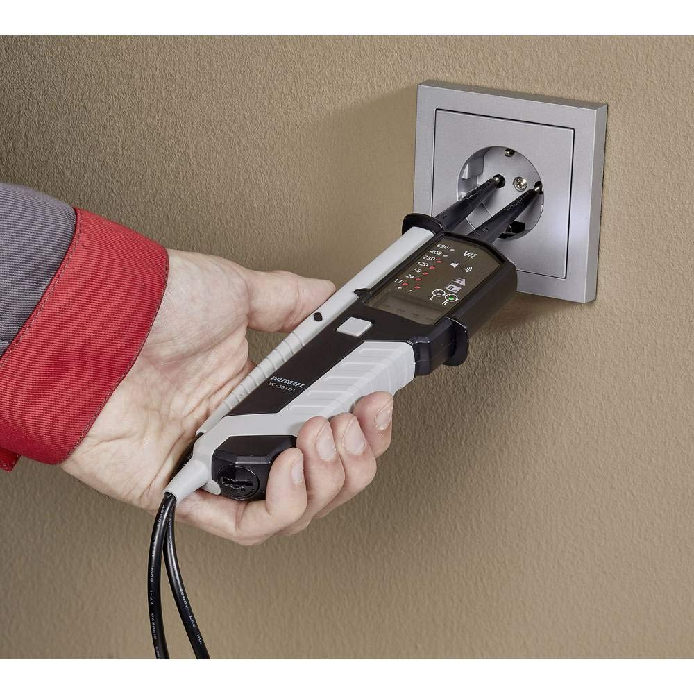
Figure 4: The VC-55 LCD tester being used to safely check the voltage and presence of live wires in a standard wall socket.
6. Maintenance
- Cleaning: Clean the device regularly with a dry, lint-free cloth. Do not use abrasive cleaners or solvents.
- Storage: Store the tester in a dry, cool place, away from direct sunlight and extreme temperatures. If storing for extended periods, remove the batteries to prevent leakage.
- Battery Replacement: Replace batteries when the low battery indicator appears on the LCD.
7. Troubleshooting
- No Display/No Power: Check battery installation and ensure batteries are not depleted. Replace if necessary.
- Inaccurate Readings: Ensure probes are making good contact with the test points. Verify the tester on a known voltage source.
- No Continuity Indication: Ensure the circuit is de-energized. Check for open circuits or high resistance.
- Tester Not Responding: Remove batteries, wait a few seconds, and reinsert them. If the issue persists, contact customer support.
8. Specifications
| Feature | Specification |
|---|---|
| Brand | VOLTCRAFT |
| Model Number | VC-55 LCD |
| Measurement Type | 2-Pole Voltage Tester |
| Safety Rating | CAT III 1000 V, CAT IV 600 V |
| Voltage Display | LCD and LED (12 V to 690 V) |
| Compliant Specifications | EN 61243-3/VDE0682 |
| Power Source | Battery Powered (2 AAA - included) |
| Min. Operating Voltage | 12 Volts |
| Max. Rated Temperature | 71 Degrees Celsius |
| Color | Black and White |
| Item Dimensions | 30.7 x 19 x 4.2 cm |
| Item Weight | 9.07 grams |
| Spare Parts Availability | 1 Year |
9. Warranty and Support
This VOLTCRAFT product is designed for durability and reliability. For information regarding warranty coverage, spare parts availability, or technical support, please refer to the documentation included with your purchase or visit the official VOLTCRAFT website. For specific inquiries, you may also contact the seller directly.


