1. Introduction
This manual provides instructions for the installation, configuration, and operation of the D-Link DGS-1210-28P Web Smart 24-Port Gigabit PoE Switch. This device is designed to provide a high-performance, cost-effective solution for small to medium-sized businesses, offering advanced management features and Power over Ethernet (PoE) capabilities.
2. Safety Information
- Ensure proper ventilation around the switch to prevent overheating.
- Do not place the switch in areas with high humidity or extreme temperatures.
- Use only the power adapter supplied with the device.
- Disconnect power before cleaning or performing maintenance.
- This device should be installed by qualified personnel in accordance with all local and national electrical codes.
3. Package Contents
Verify that your package contains the following items:
- DGS-1210-28P Web Smart 24-Port Gigabit PoE Switch
- Power Cord
- Rack Mount Kit (brackets and screws)
- Rubber Feet (for desktop installation)
- Console Cable (RJ-45 to DB-9)
- Quick Installation Guide
- CD-ROM (containing product documentation)
If any items are missing or damaged, please contact your local D-Link reseller for assistance.
4. Physical Description and Hardware Overview
The DGS-1210-28P switch features 24 Gigabit Ethernet ports with PoE support and 4 SFP slots for fiber optic connections. Below are diagrams illustrating the front and rear panels of the device.
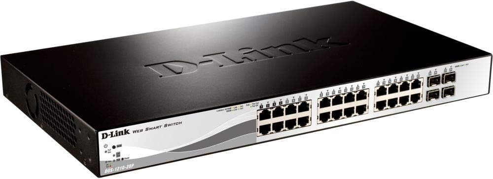
Figure 4.1: Front Panel View
This image displays the front panel of the DGS-1210-28P switch, showing 24 RJ-45 Gigabit Ethernet ports, each with LED indicators for link/activity and PoE status. To the right, there are 4 SFP (Small Form-Factor Pluggable) slots for fiber optic transceivers. The D-Link logo and model number are visible on the left side of the panel.

Figure 4.2: Rear Panel View
This image shows the rear panel of the DGS-1210-28P switch. The primary feature visible is the AC power input connector on the right side, labeled "AC LINE" with voltage and current specifications (100-240VAC, 50/60Hz, 0.5 A MAX). The D-Link brand name is embossed on the top surface of the switch casing.
4.1 Front Panel Indicators
- Power LED: Indicates the power status of the switch.
- System LED: Indicates the system status.
- Link/Act LEDs (per port): Green for Gigabit link/activity, Amber for 10/100 Mbps link/activity.
- PoE Status LEDs (per PoE port): Indicates PoE power delivery status.
4.2 Rear Panel Connectors
- AC Power Input: Connects to the provided power cord.
5. Setup
5.1 Desktop Installation
- Attach the included rubber feet to the bottom of the switch.
- Place the switch on a flat, stable surface with adequate ventilation.
5.2 Rack Installation
- Attach the two rack-mounting brackets to the side grooves of the switch using the provided screws.
- Secure the switch into a standard 19-inch equipment rack using appropriate rack screws (not included).
5.3 Connecting the Switch
- Connect your network devices (computers, servers, access points, IP cameras) to the RJ-45 ports on the front panel using standard Ethernet cables.
- For fiber optic connections, insert compatible SFP transceivers into the SFP slots and connect fiber optic cables.
- Connect the power cord to the AC power input on the rear panel of the switch and then to a suitable power outlet.
- Verify that the Power LED on the front panel illuminates.
6. Operating the Switch
6.1 Initial Access to Web-based Management
The DGS-1210-28P is a Web Smart switch, meaning it can be configured and managed via a web browser.
- Ensure your computer is connected to one of the switch's Ethernet ports.
- By default, the switch has a pre-configured IP address (e.g., 192.168.0.1). Refer to the Quick Installation Guide or product documentation for the exact default IP address.
- Configure your computer's IP address to be in the same subnet as the switch (e.g., if the switch is 192.168.0.1, set your computer to 192.168.0.10 with subnet mask 255.255.255.0).
- Open a web browser (e.g., Chrome, Firefox, Edge) and enter the switch's default IP address in the address bar.
- You will be prompted for a username and password. The default credentials are typically "admin" for both username and password. Refer to the documentation for specific defaults.
- Upon successful login, you will access the switch's web management interface, where you can configure various network settings, VLANs, QoS, PoE settings, and more.
Important: For security reasons, it is highly recommended to change the default password immediately after initial login.
6.2 Power over Ethernet (PoE) Functionality
The DGS-1210-28P supports PoE, allowing it to deliver power to compatible devices (e.g., IP phones, wireless access points, IP cameras) over the Ethernet cable. This eliminates the need for separate power outlets for these devices.
- Connect PoE-compatible devices to any of the 24 Gigabit Ethernet ports.
- The switch will automatically detect and provide power to compliant devices.
- Monitor PoE status via the port LEDs or the web management interface.
- The total power budget for the switch is 193 Watts. Ensure the total power consumption of connected PoE devices does not exceed this limit.
7. Maintenance
- Cleaning: Use a soft, dry cloth to clean the exterior of the switch. Do not use liquid or aerosol cleaners.
- Firmware Updates: Periodically check the D-Link support website for firmware updates to ensure optimal performance and security. Follow the instructions provided with the firmware update package.
- Ventilation: Ensure that the ventilation openings on the switch are not blocked to prevent overheating.
- Backup Configuration: Regularly back up your switch configuration settings through the web management interface to facilitate quick recovery in case of a reset or failure.
8. Troubleshooting
| Problem | Possible Cause | Solution |
|---|---|---|
| No Power LED indication | Power cord not connected or power outlet issue. | Verify power cord connection to the switch and power outlet. Test the outlet with another device. |
| No Link/Act LED on a connected port | Faulty cable, incorrect cable type, or device not powered on. | Check the Ethernet cable for damage. Ensure the connected device is powered on and functioning correctly. Try a different port or cable. |
| Cannot access web management interface | Incorrect IP address, subnet mismatch, or browser issue. | Verify the switch's IP address and your computer's IP settings. Ensure they are in the same subnet. Clear browser cache or try a different browser. Reset the switch to factory defaults if necessary (refer to documentation for procedure). |
| PoE device not receiving power | Device not PoE compliant, cable issue, or power budget exceeded. | Ensure the device is PoE compliant. Check the Ethernet cable. Verify the total PoE power consumption in the web interface and ensure it does not exceed 193 Watts. |
9. Specifications
| Model | DGS-1210-28P |
| Ports | 24 x 10/100/1000BASE-T PoE Ports, 4 x Gigabit SFP Ports |
| PoE Standard | IEEE 802.3af/at |
| Total PoE Power Budget | 193 Watts |
| Switching Capacity | 56 Gbps |
| Forwarding Rate | 41.67 Mpps |
| MAC Address Table Size | 16K entries |
| Jumbo Frame | 10,000 Bytes |
| Dimensions (W x D x H) | 440 x 210 x 44 mm (17.32 x 8.27 x 1.73 inches) |
| Weight | 3.63 kg (8 lbs) |
| Power Input | 100-240 VAC, 50/60 Hz Internal Universal Power Supply |
| Operating Temperature | 0°C to 50°C (32°F to 122°F) |
| Storage Temperature | -20°C to 70°C (-4°F to 158°F) |
| Operating Humidity | 0% to 95% non-condensing |
10. Warranty and Support
D-Link provides a limited warranty for this product. For detailed warranty information, please refer to the warranty card included with your product or visit the official D-Link website.
For technical support, product documentation, and firmware updates, please visit the D-Link support portal:
You can also find additional resources and community forums on the D-Link website.


