1. Introduction
This manual provides comprehensive instructions for the installation, operation, and maintenance of the Visionis FPC-5012 Electromagnetic Lock Kit. This standalone access control system is designed to secure outswinging doors, allowing controlled entry and exit via wireless remote and an exit button. Please read this manual thoroughly before installation and operation to ensure proper functionality and safety.
2. Components Included
The Visionis FPC-5012 kit includes the following components:
- (1) VIS-ML600LED: 600lbs Indoor Electric Lock with LED Sensor
- (1) VIS-8004: 1-Channel Receiver 315mhz 11-24 VAC/DC
- (2) VIS-8005: Fixed Code Transmitter, Pre-coded Wireless Remote
- (2) VISCP200: 12v 2000ma Power Supply
- (1) VIS-7000: Green Push to Exit Button Illuminated with LED

3. Product Specifications
| Feature | Specification |
|---|---|
| Brand | Visionis |
| Model Number | FPC-5012 |
| Power Source | DC |
| Connectivity Technology | Wireless |
| Installation Type | Screw-In |
| Alert Type | Remote Control |
| Item Weight | 7 Pounds |
| Voltage | 12 Volts (Dual Voltage 12V/24V selectable) |
| Control Method | Remote |
| Maximum Range (Remote) | 300 Feet |
| Maglock Holding Force | 600lbs |
| Maglock Power Consumption (600lb) | 500mA @ 12V, 250mA @ 24V |
4. Setup and Installation
4.1 Important Considerations
- This electromagnetic lock is designed for indoor use only. Do not install in outdoor applications.
- This kit is specifically for outswinging doors. For inswinging door applications, please refer to Visionis kits FPC-5191 (300lb), FPC-5192 (600lb), or FPC-5193 (1200lb) which include the necessary brackets.
- The maglock can be installed on both wood and metal doors.
- Ensure the door and frame are strong enough to withstand the specified holding force of the maglock.
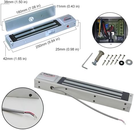
4.2 Maglock Features
- Dual Voltage: The maglock supports both 12V and 24V operation. The default voltage is 12V. A jumper inside the terminal allows voltage selection. Refer to the user manual for detailed instructions on changing the voltage.
- Door Status Monitoring: Each maglock includes a white wire built into the cap for door status monitoring. This can be connected as a hard-wired alarm contact to your system. If not used, this wire can be cut.
- Low Power Consumption: The 600lb maglock uses 500mA at 12V and 250mA at 24V.
- LED Indicator: An integrated LED light indicates the lock status. Red indicates unlocked, green indicates locked.
- Fail-Safe Operation: All Visionis maglocks are fail-safe, meaning they will unlock when power is lost.

4.3 Installation Steps (Outswinging Door)
Follow these steps for installing the electromagnetic lock on an outswinging door:
- Prepare the Door Frame: Use the provided installation template to mark and drill holes on the door frame for the mounting plate.
- Mount the Lock Body: Separate the cover from the lock body. Secure the mounting plate to the door frame using the provided screws. Ensure the wire for the lock passes through the designated hole. Hang the lock body onto the mounting plate and fasten its screws.
- Install the Armature Plate: Insert the guide pins into the armature plate. Attach the armature plate to the door leaf, ensuring it aligns with the maglock. Fasten the inner hex nut on the back side of the door leaf and secure the screw on the armature plate. Add rubber washers and metal washers if needed to ensure a complete fit with the magnetic lock.
- Connect Wiring: Refer to the wiring diagram in Section 4.4 for detailed connections.
4.4 Wiring Instructions
The following diagram illustrates the wiring connections for the FPC-5012 kit components:

- Connect the Red wire from the Maglock to the Red wire of the first Power Supply.
- Connect the Red wire from the Exit Button to the Red wire of the first Power Supply.
- Connect the Black wire from the first Power Supply to the COM Yellow wire of the Wireless Receiver.
- Connect the Black wire from the Maglock to the COM Green wire of the Exit Button.
- Connect the NC Orange wire from the Exit Button to the White wire of the Wireless Receiver.
- Connect the Red wire from the second Power Supply to the Red wire of the Wireless Receiver.
- Connect the Black wire from the second Power Supply to the Black wire of the Wireless Receiver.
Important Safety Note:
- Before purchasing or installing this kit, it is recommended that the customer checks with their local fire authority to see if there is any additional product they may need in order to comply with the local fire codes.
- Make sure to cut off the connectors on both power supplies, then strip the wire leads before installing.
- In order to properly install this kit it is recommended that you use 18/2 or 20/2 gauge wire.
- Make sure that when you are installing this kit you have all components turned off. We are not responsible for any type of short circuits.
- We are not responsible for the improper installation of our product(s) or any type of fees that can be incurred by not complying with your local fire authority.
- If you are not handy with electrical components please consult with a certified electrician or locksmith.
5. Operating Instructions
5.1 Wireless Receiver and Remotes (VIS-8004 & VIS-8005)
The VIS-8004 is a 1-Channel 315MHz RF receiver supplied with an antenna. The VIS-8005 is a one-channel remote. Both are commonly used for opening doors, garage doors, and gates. You just press the button on the remote control, and the door will unlock.

- 4-Second Delay: The lock releases for 4 seconds and then re-locks. (Default function)
- Toggle Switch: Press once to unlock, press again to lock.
- Press ON: The lock remains unlocked as long as the remote button is pressed.
- Latched: The lock remains unlocked until a second button on the remote is pressed (requires a 2-button remote like VIS-8008 and VIS-8007 receiver).
Refer to the receiver's specific manual for detailed programming instructions for each function.
5.2 Indoor Exit Button (VIS-7000)
The Visionis 7000 is a standard-sized push-to-exit button. It is suitable for residential, commercial, and industrial applications. It features an illuminated backlight and a stainless steel plate for a professional look. This exit button is for indoor use only.

6. Maintenance
To ensure optimal performance and longevity of your Visionis FPC-5012 system, regular maintenance is recommended:
- Cleaning: Periodically clean the surface of the electromagnetic lock and armature plate with a soft, dry cloth. Avoid abrasive cleaners or solvents.
- Inspection: Regularly inspect all wiring connections for any signs of wear, damage, or loose connections. Ensure all screws are tight.
- Functionality Test: Periodically test the system's functionality by using the remote controls and the exit button to ensure the lock engages and disengages correctly.
- Power Supply: Ensure power supplies are free from damage and are providing stable power to the system.
7. Troubleshooting
If you encounter issues with your Visionis FPC-5012 system, consider the following troubleshooting steps:
- Lock Not Engaging/Disengaging:
- Check all power connections to ensure they are secure and receiving power.
- Verify the power supplies are functioning correctly.
- Ensure the armature plate and maglock are properly aligned and free of debris.
- Confirm the remote controls are programmed correctly and have working batteries.
- Check the wiring connections to the receiver and exit button as per the wiring diagram.
- LED Indicator Not Working:
- Ensure the maglock is receiving power.
- Check for any loose internal connections within the maglock.
- Remote Control Range Issues:
- Ensure the receiver's antenna is unobstructed.
- Replace remote control batteries if necessary.
- Minimize interference from other wireless devices.
If problems persist after attempting these steps, please contact Visionis customer support for assistance.
8. Warranty and Support
The Visionis FPC-5012 Electromagnetic Lock Kit comes with a 3-year warranty from the date of purchase. This warranty covers defects in materials and workmanship under normal use.
For technical support, warranty claims, or any questions regarding your product, please visit the official Visionis website or contact their customer service department. Ensure you have your product model number (FPC-5012) and proof of purchase available when seeking support.


