1. Introduction
This manual provides comprehensive instructions for the installation, operation, and maintenance of the Legrand Watt Stopper LMRC-212 Digital 2-Relay Room Controller. This device is designed for efficient lighting control in commercial and industrial applications, integrating occupancy sensors, daylighting controls, and switches within a Digital Lighting Management (DLM) system.
2. Safety Information
WARNING: Risk of electric shock. Installation and servicing must be performed by qualified personnel only. Disconnect power at the circuit breaker or fuse before installing or servicing. Follow all national and local electrical codes.
- Ensure all wiring connections are secure and comply with local electrical codes.
- Do not install in wet or damp locations.
- Do not exceed the specified electrical ratings of the device.
- This device is intended for indoor use only.
3. Product Overview
The LMRC-212 is a digital 2-relay room controller that serves as a foundational component of a Watt Stopper Digital Lighting Management (DLM) system. It features two relays for switching loads and two 0-10 volt outputs for dimmable loads, such as electronic ballasts. The device facilitates integration with various lighting control components via RJ-45 connectivity.
Key Features:
- Digital 2-Relay Room Controller
- RJ-45 Connectivity for DLM network integration
- On/Off/0-10 Volt Dimming capabilities
- Supports 120/277V, 20 Amps
- Provides 24VDC, 250 mA output for DLM devices

Figure 3.1: Front view of the LMRC-212 controller.

Figure 3.2: Product label on the LMRC-212 controller detailing electrical specifications and certifications.
4. Specifications
| Feature | Detail |
|---|---|
| Model Number | LMRC-212 |
| Input Voltage | 120/277 VAC, 50/60Hz |
| Output Current (DLM) | 250 mA @ 24VDC |
| Maximum Load (Ballast/Incandescent) | 20 Amps |
| Motor Load | 1 HP @ 120VAC |
| Maximum Combined Load | 20 Amps |
| Dimming Outputs | Two 0-10V dimming outputs |
| Connectivity | RJ-45 |
| Mounting Type | Wall Mount |
| Dimensions | 7.7 x 7.3 x 4.4 inches |
| Weight | 1 pound |
| Certifications | UL 2043 Plenum Rated, cULus Listed |
5. Installation and Wiring
Before beginning installation, ensure that power to the circuit is disconnected at the main breaker. The LMRC-212 is designed for wall mounting and integrates into a Digital Lighting Management (DLM) network.
Wiring Connections:
- Power Input: Connect the 120/277V AC power supply to the designated terminals.
- Load Connections: Connect lighting loads to Load A and Load B terminals. The LMRC-212 supports two independent relays.
- 0-10V Dimming Outputs: Connect 0-10V dimmable ballasts or LED drivers to the respective 0-10V Dimming Output terminals (Violet + and Grey - for each load).
- DLM Network Connection: Connect the LMRC-212 to the DLM Local Network using an RJ-45 cable. Important: Connect only to a DLM Local Network, not to Ethernet.
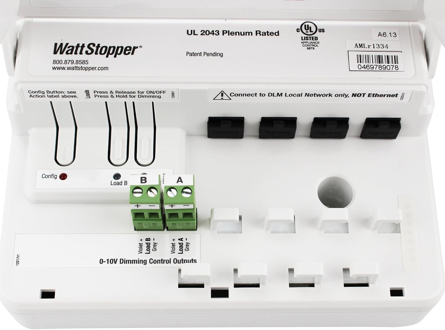
Figure 5.1: Internal wiring diagram of the LMRC-212, highlighting Load A, Load B, 0-10V Dimming Outputs, and RJ-45 DLM network ports.
Configuration Button:
The device includes a configuration button (labeled "Config") for initial setup and pairing with other DLM devices. Refer to the DLM system guide for detailed configuration procedures.
6. Operation
Once installed and configured within a DLM system, the LMRC-212 controls connected lighting loads based on inputs from DLM occupancy sensors, daylight sensors, and wall switches.
Manual Control (via connected DLM switches):
- On/Off: A quick press and release of a connected DLM switch button will toggle the associated load On or Off.
- Dimming: Press and hold a connected DLM switch button to adjust the dimming level of the associated 0-10V dimmable load. Release the button when the desired light level is reached.
The specific behavior and grouping of loads are determined during the DLM system configuration process.
7. Maintenance
The LMRC-212 is designed for long-term, reliable operation with minimal maintenance. Periodically inspect the device and its connections to ensure proper functioning.
- Cleaning: Disconnect power before cleaning. Wipe the exterior with a soft, dry cloth. Do not use abrasive cleaners or solvents.
- Inspection: Annually inspect wiring connections for tightness and signs of wear or damage.
- Firmware: For firmware updates or advanced diagnostics, consult a qualified Legrand Watt Stopper technician or refer to the latest DLM system documentation.
8. Troubleshooting
If the LMRC-212 or connected lighting loads are not functioning as expected, perform the following basic troubleshooting steps:
- No Power:
- Check the circuit breaker or fuse supplying power to the controller.
- Verify all power connections to the LMRC-212 are secure.
- Loads Not Responding:
- Ensure the DLM network cable (RJ-45) is securely connected to the LMRC-212 and other DLM devices.
- Verify that the connected DLM switches or sensors are properly configured and communicating with the LMRC-212.
- Check the wiring to the lighting loads (Load A, Load B) and 0-10V dimming outputs.
- Confirm that the loads themselves are functional.
- Dimming Issues:
- Ensure that the connected fixtures are indeed 0-10V dimmable and compatible with the LMRC-212.
- Check the polarity of the 0-10V dimming wires (Violet + and Grey -).
For persistent issues, contact Legrand Watt Stopper technical support.
9. Warranty and Support
For warranty information, please refer to the official Legrand Watt Stopper warranty statement available on their website or included with the product packaging. For technical assistance, product support, or to report issues, please contact:
Watt Stopper Technical Support:
Phone: 800.879.8585
Website: www.wattstopper.com