1. Introduction
This manual provides instructions for the installation, operation, and maintenance of your Cisco SG100-24-NA 24-Port Gigabit Switch. This unmanaged switch is designed to provide high-performance network connectivity for small to medium-sized businesses, offering ease of use and simple setup without complex configuration.
Please read this manual thoroughly before using the device to ensure proper setup and to maximize its performance and longevity.
2. Product Overview
2.1 Key Features
- 24 Gigabit Ethernet Ports: Provides high-speed wired connections for multiple devices.
- 2 Combo Mini-GBIC Ports: Offers flexible uplink options using fiber optic or copper connections.
- Unmanaged Switch: Plug-and-play operation requires no software configuration.
- High Performance: Supports a switching capacity of 48 Gbps and a forwarding capacity of 35.7 mpps for efficient data transfer.
- Energy Efficient: Designed for optimal power consumption.
- Compact Design: Suitable for desktop or rack-mount installations.
2.2 Package Contents
The Cisco SG100-24-NA package typically includes:
- Cisco SG100-24-NA 24-Port Gigabit Switch
- Power Cord
- Mounting Kit (for rack-mount, if applicable)
- Quick Start Guide
Note: Contents may vary slightly depending on the region and specific product bundle.
2.3 Physical Description
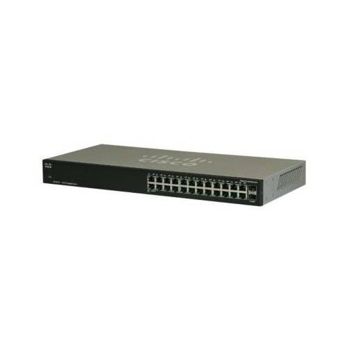
Figure 1: Front View of the Cisco SG100-24-NA Switch. This image shows the front panel of the switch, featuring 24 RJ-45 Gigabit Ethernet ports and status indicator LEDs for each port. The Cisco logo is visible on the left.

Figure 2: Rear View of the Cisco SG100-24-NA Switch. This image displays the rear panel, including the power input connector and product label with serial number and regulatory information.

Figure 3: Side View of the Cisco SG100-24-NA Switch. This image illustrates the side panel, highlighting the ventilation grilles designed for heat dissipation to ensure optimal performance.
3. Setup Instructions
Follow these steps to set up your Cisco SG100-24-NA Gigabit Switch:
3.1 Site Preparation
- Location: Place the switch on a flat, stable surface or mount it in a standard 19-inch equipment rack. Ensure adequate ventilation around the device.
- Power: Connect the switch to a grounded power outlet. Ensure the power source meets the switch's electrical requirements.
- Environment: Avoid placing the switch near heat sources, in direct sunlight, or in areas with excessive dust or moisture.
3.2 Connecting the Switch
- Connect Power: Plug the provided power cord into the power input on the rear panel of the switch and then into a suitable electrical outlet.
- Connect Network Devices: Use standard Ethernet cables (Cat5e or higher) to connect your network devices (computers, servers, access points, routers) to any of the 24 RJ-45 Gigabit Ethernet ports on the front panel.
- Connect Uplink (Optional): If using the Mini-GBIC ports for fiber or copper uplinks, insert the appropriate SFP module (not included) into one of the combo Mini-GBIC slots and connect the corresponding cable.
- Verify Connections: Once devices are connected, check the LED indicators on the front panel. A solid green LED typically indicates a valid link, and a blinking LED indicates network activity.
The Cisco SG100-24-NA is an unmanaged switch, meaning it operates automatically without requiring any software configuration. Once powered on and connected, it will begin forwarding network traffic.
4. Operating Instructions
The Cisco SG100-24-NA is designed for simple, plug-and-play operation. No user configuration is required for basic functionality.
4.1 Power On/Off
- Power On: Connect the power cord to the switch and a power outlet. The switch will power on automatically.
- Power Off: Disconnect the power cord from the switch or the power outlet.
Note: There is no dedicated power button on this model.
4.2 LED Indicators
Each RJ-45 port has an associated LED indicator:
- Solid Green: Indicates a valid network link at Gigabit (1000 Mbps) speed.
- Solid Amber: Indicates a valid network link at 10/100 Mbps speed.
- Blinking Green/Amber: Indicates network activity (data transmission/reception) on that port.
- Off: No link detected or port is inactive.
A system LED (usually on the far left) indicates the overall status of the switch. Refer to the Quick Start Guide for specific system LED behavior.
5. Maintenance
The Cisco SG100-24-NA switch requires minimal maintenance to ensure optimal performance and longevity.
5.1 Cleaning
- Periodically clean the exterior of the switch with a soft, dry, lint-free cloth.
- Do not use liquid or aerosol cleaners, as they may damage the device.
- Ensure ventilation openings are free from dust and obstructions.
5.2 Environmental Considerations
- Operate the switch within its specified temperature and humidity ranges (refer to specifications).
- Ensure proper airflow to prevent overheating.
6. Troubleshooting
If you encounter issues with your Cisco SG100-24-NA switch, refer to the following common troubleshooting steps:
6.1 No Power
- Ensure the power cord is securely connected to both the switch and a working electrical outlet.
- Verify that the power outlet is functional by plugging in another device.
- Check the system LED on the switch; if it's off, there might be a power issue.
6.2 No Link Light on Port
- Ensure the Ethernet cable is securely connected to both the switch port and the connected device.
- Try a different Ethernet cable to rule out a faulty cable.
- Connect the device to a different port on the switch.
- Verify that the connected device is powered on and functioning correctly.
6.3 Slow Network Connection
- Ensure all connected devices and cables support Gigabit Ethernet for optimal speed.
- Check for excessive network traffic or bandwidth-intensive applications.
- Verify that the link light for the port is solid green (Gigabit speed) and not amber (10/100 Mbps).
- Restart the switch and connected devices.
7. Specifications
| Model | SG100-24-NA |
| Ports | 24 x 10/100/1000 Mbps RJ-45, 2 x Combo Mini-GBIC (shared with 2 RJ-45 ports) |
| Switching Capacity | 48 Gbps |
| Forwarding Capacity | 35.7 mpps |
| Jumbo Frame Support | 9216 bytes |
| MAC Address Table Size | 8000 entries |
| Dimensions (L x W x H) | Approximately 21.75 x 12.25 x 4 inches (Package Dimensions) |
| Weight | Approximately 6.74 pounds |
| Power | 100-240V AC, 50-60 Hz, internal universal power supply |
| Operating Temperature | 0° to 40°C (32° to 104°F) |
| Storage Temperature | -20° to 70°C (-4° to 158°F) |
| Operating Humidity | 10% to 90% non-condensing |
Note: Specifications are subject to change without notice. For the most current information, please refer to the official Cisco product page or documentation.
8. Warranty and Support
8.1 Product Warranty
Cisco products typically come with a limited hardware warranty. The exact terms and duration of the warranty may vary by region and product. Please refer to the warranty information included with your product packaging or visit the official Cisco website for detailed warranty statements.
8.2 Technical Support
For technical assistance, product documentation, software downloads, and community forums, please visit the official Cisco Support website. You may need your product's serial number for support inquiries.
Cisco Support Website: https://www.cisco.com/c/en/us/support/index.html


