
Hantek DSO5102P
Contents
Hantek DSO5102P Digital Oscilloscope User Manual
Model: DSO5102P | Brand: Hantek
1. Introduction and Overview
The Hantek DSO5102P is a 2-channel digital storage oscilloscope designed for accurate and reliable signal analysis. It features a 100 MHz bandwidth and a 1 GSa/s real-time sampling rate, making it suitable for a wide range of electronic testing and measurement applications. The device is equipped with a 7-inch WVGA (800x480) color display for clear waveform visualization and offers a record length of up to 40K points. Its robust design and comprehensive features provide an efficient tool for hobbyists, students, and professionals.
2. Package Contents
Upon unpacking, please verify that all items listed below are present and in good condition:
- Hantek DSO5102P Digital Oscilloscope Unit
- Two (2) Oscilloscope Probes
- One (1) USB Cable
- One (1) Software CD
- One (1) EU Power Cable

This image displays the Hantek DSO5102P Digital Oscilloscope along with its standard accessories. The package includes the main oscilloscope unit, two oscilloscope probes, a USB cable for PC connection, a software CD, and an EU standard power cable.
3. Product Features
- Bandwidth: 100 MHz
- Real-time Sample Rate: 1 GSa/s
- Display: 7-inch WVGA (800 x 480) Color Display
- Record Length: Up to 40K points
- Trigger Functions: Edge, Video, Pulse, Slope
- Automatic Measurements: 32 types of waveform automatic measurements
- Connectivity: USB interface for data transfer and U-disk storage
- Heat Dissipation: Designed for rapid heat dissipation for prolonged use

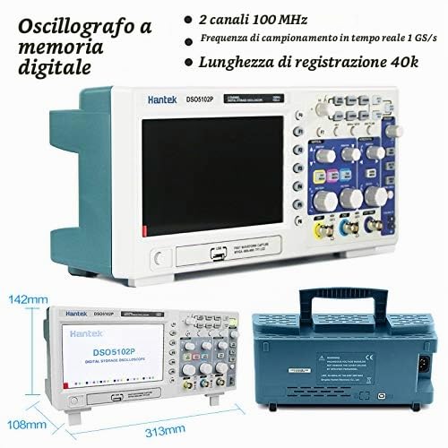
A detailed front view of the Hantek DSO5102P Digital Oscilloscope, emphasizing its key specifications such as 100MHz bandwidth and 1GSa/s real-time sampling rate. This image provides a general overview of the device's appearance.
4. Setup
4.1 Initial Inspection
Before connecting the oscilloscope, inspect the unit and all accessories for any signs of damage. If any damage is found, contact your vendor immediately.
4.2 Power Connection
- Ensure the oscilloscope's power switch is in the OFF position.
- Connect the provided EU power cable to the power input on the rear panel of the oscilloscope.
- Plug the other end of the power cable into a suitable AC power outlet. Note: Some users may receive a power cable with a non-standard plug for their region (e.g., UK plug in EU). An appropriate adapter or replacement cable may be required.
4.3 Probe Connection and Calibration
- Connect the oscilloscope probes to the CH1 and CH2 input BNC connectors on the front panel.
- Attach the probe ground clip to the oscilloscope's ground terminal.
- To calibrate the probes, connect the probe tip to the probe compensation output (usually a square wave test signal) on the front panel.
- Adjust the compensation trimmer on the probe until a flat-top square wave is displayed on the screen.

This composite image presents the Hantek DSO5102P Digital Oscilloscope from various angles, including the front panel, the rear panel with power input and ventilation, and side views, illustrating its compact design and integrated handle.
5. Operating Instructions
5.1 Powering On and Basic Display
- Press the power switch on the front panel to turn on the oscilloscope.
- The device will perform a self-test and display the main waveform interface.
- Use the VERTICAL controls (VOLTS/DIV knob and POSITION knob) for each channel (CH1, CH2) to adjust the vertical scale and position of the waveform.
- Use the HORIZONTAL controls (SEC/DIV knob and POSITION knob) to adjust the time base and horizontal position of the waveform.
5.2 Triggering
The trigger system stabilizes repetitive waveforms and captures single-shot events. Use the TRIGGER controls to set the trigger level, mode (Edge, Video, Pulse, Slope), and source.
5.3 Automatic Measurements
The DSO5102P supports 32 types of automatic waveform measurements, providing quick access to parameters like frequency, period, peak-to-peak voltage, RMS, and more. Access these functions via the menu buttons on the front panel.

This image displays the oscilloscope's capability to perform 32 types of automatic waveform measurements, showing multiple examples of analyzed waveforms and data on the screen, which aids in quick and accurate signal analysis.
5.4 Math Functions
The oscilloscope includes mathematical functions such as addition, subtraction, multiplication, division, and Fast Fourier Transform (FFT) for advanced signal analysis. These functions can be accessed through the dedicated MATH menu button.
5.5 USB Data Transfer and Storage
The front panel features a USB host port for connecting a U-disk (USB flash drive) to save waveform data, screenshots, and instrument settings. A USB device port is also available for connecting the oscilloscope to a PC for remote control and data transfer using the provided software.
This diagram highlights the USB data transfer functionality of the oscilloscope, allowing users to save waveform data and screenshots to a U-disk or transfer them to a computer for further analysis and documentation.

This image provides a labeled diagram of the Hantek DSO5102P's front panel, indicating the location and function of the LCD display, various option buttons, executive control knobs, power switch, USB interface, analog channel input signals (CH1, CH2), and the external trigger input.

This image showcases the oscilloscope's ability to accurately display a variety of electrical signals, including sine waves, square waves, and more complex waveforms, demonstrating its versatility in signal visualization.
6. Maintenance
6.1 Cleaning
To maintain the oscilloscope, clean the exterior surfaces with a soft, damp cloth. Avoid using abrasive cleaners or solvents that could damage the casing or screen. Ensure the device is powered off and unplugged before cleaning.
6.2 Ventilation and Heat Dissipation
The DSO5102P is designed with efficient heat dissipation to ensure safe and prolonged operation. Ensure that the ventilation grilles on the rear and sides of the unit are not obstructed during use. Operating the device in a well-ventilated area will help prevent overheating.

An image of the oscilloscope's rear panel, emphasizing its design for rapid heat dissipation. This feature ensures safe and prolonged operation of the device by preventing overheating.
7. Troubleshooting
- No Power: Check the power cable connection and ensure the power outlet is functional. Verify that the correct power cable for your region is being used.
- No Waveform Display: Ensure probes are correctly connected to the input channels and the signal source. Check the vertical and horizontal scale settings. Adjust the trigger level.
- Unstable Waveform: Adjust the trigger settings (level, mode, source) to stabilize the waveform. Ensure the probe compensation is correctly set.
- Software Issues (PC Connection): If experiencing conflicts with PC software (e.g., with Windows 10), try reinstalling the drivers from the provided CD or checking the official Hantek website for updated drivers.
- Noisy Signal: Ensure proper grounding of the oscilloscope and the circuit under test. Check for external electromagnetic interference.
8. Specifications
| Feature | Specification |
|---|---|
| Manufacturer | Hantek |
| Model Number | DSO5102P (20-010-718) |
| Bandwidth | 100 MHz |
| Real-time Sample Rate | 1 GSa/s |
| Channels | 2 |
| Display | 7-inch WVGA (800 x 480) Color Display |
| Record Length | 40K |
| Trigger Functions | Edge, Video, Pulse, Slope |
| Item Weight | 2.5 Kilograms |
| Product Dimensions | 31.3 x 14 x 11 cm |
| Batteries Required | No |
9. Warranty and Support
For warranty information, please refer to the documentation provided with your purchase or contact your retailer. Hantek's official website (www.hantek.com) may offer additional support resources, updated drivers, and contact information for technical assistance. Users have reported varying experiences with post-sales support; it is recommended to consult the official channels for the most current information.
Ask a question about this manual
Ask about setup, troubleshooting, compatibility, parts, safety, or missing instructions. Manuals+ will review the question and use this page’s manual context to help answer it.