
1. Product Overview
The Accusize Industrial Tools Disc and Rotor/Ball Joint Gage Set, model 0510-0917, is a precision measurement instrument designed for automotive and industrial applications. It is used to accurately measure various forms of runout and wear in mechanical components.
Key applications include:
- Checking ball joint wear.
- Measuring disc rotor runout.
- Assessing tire and wheel runout.
- Evaluating gear backlash.
- Determining valve guide wear.
This set is designed to meet state inspection requirements for various measurements.
2. Components
The 0510-0917 gage set includes the following components, housed in a hardened, strong case for protection and organization:
- Dial Gauge: A 0-1 inch range dial indicator with 0.001 inch resolution, AGD 2 style, featuring a satin chrome finish.
- Flexible Arm: A stem holder with approximately 360-degree maneuverability, measuring 13.77 inches in length.
- Vise Grip / Locking Plier: A 7-inch locking plier for secure holding and clamping of objects.
- Protective Case: A durable case for storage and transport.
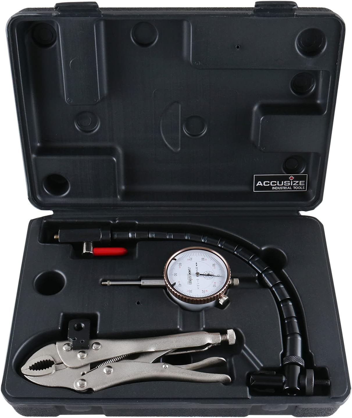
Image 2.1: The complete Accusize Industrial Tools Disc and Rotor/Ball Joint Gage Set, model 0510-0917, displayed within its protective carrying case. The dial indicator, flexible arm, and locking plier are visible, securely nested in custom-fit compartments.
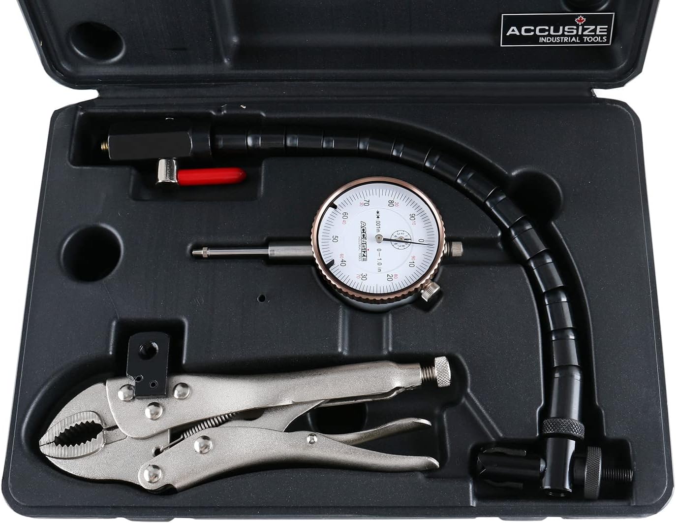
Image 2.2: A closer view of the Accusize dial gauge and its flexible arm attachment. The dial face shows measurements in inches with 0.001 inch increments, and the flexible arm is connected to a mounting block.
3. Setup and Assembly
Proper setup is crucial for accurate measurements. Follow these steps to assemble and prepare the gage set:
- Unpack Components: Carefully remove the dial gauge, flexible arm, and locking plier from the protective case.
- Attach Flexible Arm to Locking Plier: The flexible arm typically attaches to the locking plier via a threaded connection or a clamp mechanism. Ensure it is securely fastened.
- Attach Dial Gauge to Flexible Arm: Mount the dial gauge onto the flexible arm. The stem of the dial gauge usually slides into a holder on the flexible arm and is secured with a set screw or clamp. Ensure the dial gauge is firmly held and its plunger can move freely.
- Position the Assembly: Use the locking plier to firmly attach the entire assembly to a stable, non-moving part of the vehicle or workpiece adjacent to the component being measured. For disc rotor runout, this might be the caliper bracket or a suspension component.
- Adjust Flexible Arm: Manipulate the flexible arm to position the dial gauge's plunger perpendicular to the surface being measured. Once positioned, tighten the locking mechanism on the flexible arm to prevent movement. Some flexible arms may require rotating a nut to remove slack before locking the lever.

Image 3.1: The Accusize dial gauge and flexible arm assembly, with the flexible arm securely mounted to the locking plier. This configuration is ready for attachment to a workpiece for measurement.
4. Operating Instructions
This section outlines the general procedure for using the gage set for various measurements. Specific procedures may vary slightly depending on the component being inspected.
4.1 General Measurement Procedure
- Secure the Gage: Attach the locking plier to a stable, non-moving part near the component to be measured. Ensure the plier is clamped firmly and the assembly is stable.
- Position the Dial Gauge: Adjust the flexible arm so the dial gauge's plunger makes contact with the surface of the component to be measured. The plunger should be perpendicular to the surface for accurate readings.
- Preload the Plunger: Gently push the dial gauge against the surface until the plunger retracts slightly, indicating a preload. This ensures continuous contact during measurement.
- Zero the Dial: Rotate the outer bezel of the dial gauge until the '0' mark aligns with the needle.
- Perform Measurement: Slowly rotate the component (e.g., disc rotor, wheel) or move the component through its range of motion (e.g., ball joint). Observe the maximum and minimum readings on the dial gauge.
- Calculate Runout/Wear: The difference between the maximum and minimum readings represents the total runout or wear. Compare this value to the manufacturer's specifications or relevant inspection standards.
Image 4.1: The Accusize dial gauge positioned to measure the runout of a brake rotor. The flexible arm is clamped to a stable part of the vehicle, and the dial gauge's plunger is in contact with the rotor surface.
4.2 Specific Applications
- Disc Rotor Runout: Mount the gage to a stable part of the suspension or caliper. Position the plunger against the rotor face, near the outer edge. Rotate the rotor slowly and record the total indicated runout.
- Ball Joint Wear: Secure the gage to a stable chassis component. Position the plunger against the ball joint housing or a related component. Apply upward/downward force or side-to-side force to the wheel/tire assembly and observe movement on the dial.
- Tire and Wheel Runout: With the wheel mounted, secure the gage to a stable point. Position the plunger against the tire sidewall or wheel rim. Rotate the wheel and record the runout.
5. Maintenance and Care
Proper maintenance ensures the longevity and accuracy of your gage set.
- Cleaning: After each use, wipe down all components with a clean, soft cloth. For stubborn grime, a mild cleaning solution can be used, ensuring all moisture is removed afterward. Avoid harsh chemicals that may damage the finish or internal mechanisms.
- Lubrication: Periodically apply a light coat of precision instrument oil to the dial gauge's plunger and any moving parts of the flexible arm to ensure smooth operation.
- Storage: Always store the gage set in its provided protective case when not in use. This prevents damage from impacts, dust, and moisture. Store in a dry environment.
- Calibration: For critical applications, periodic calibration of the dial gauge by a certified laboratory is recommended to maintain accuracy.
6. Troubleshooting
If you encounter issues during operation, consider the following common problems and solutions:
| Problem | Possible Cause | Solution |
|---|---|---|
| Inaccurate readings |
|
|
| Flexible arm does not hold position |
|
|
| Dial gauge plunger sticks or moves roughly |
|
|
7. Specifications
| Feature | Detail |
|---|---|
| Model Number | 0510-0917 |
| Brand | Accusize Industrial Tools |
| Dial Gauge Range | 0-1 inch |
| Dial Gauge Resolution | 0.001 inch |
| Dial Gauge Style | AGD 2 |
| Flexible Arm Length | 13.77 inches |
| Locking Plier Size | 7 inches |
| Material | Stainless Steel (components) |
| Item Weight | 2.86 pounds (1.3 Kilograms) |
| Product Dimensions (L x W x H) | 3.15 x 8.27 x 11.42 inches |
| UPC | 641799799975 |
8. Warranty and Support
For warranty information, technical support, or replacement parts, please contact Accusize Industrial Tools directly. Refer to the product packaging or the official Accusize Industrial Tools website for the most current contact details and warranty policy.
Online Resources:
- Visit the official Accusize Industrial Tools Store on Amazon for product information and updates.


