1. Introduction
The PeakTech 3385 is a robust analog multimeter designed for a variety of electrical measurements. This versatile device is suitable for both professional and educational use, offering functions such as AC/DC voltage, AC/DC current, resistance, continuity testing, and dB measurements. Its analog display provides clear readings, and the durable, non-slip housing ensures protection against impacts.
This manual provides essential information for the safe and effective operation of your PeakTech 3385 multimeter. Please read it thoroughly before use and keep it for future reference.
2. Safety Information
Always observe the following safety precautions to prevent electric shock or damage to the meter:
- The PeakTech 3385 is rated for CAT III 600 V. Do not attempt to measure voltages exceeding this rating.
- Before making any measurements, ensure the function switch is set to the correct range.
- Never measure voltage with the test leads connected to the current input terminals (mA/A).
- Inspect test leads for damaged insulation or exposed metal before each use. Replace damaged leads immediately.
- Do not use the meter if it appears damaged or if the case is open.
- Be cautious when working with voltages above 30V AC RMS, 42V peak, or 60V DC. These voltages pose a shock hazard.
- Always disconnect power to the circuit and discharge all high-voltage capacitors before performing resistance or continuity tests.
- Replace batteries as soon as the low battery indicator appears to ensure accurate readings.

Figure 2.1: The PeakTech 3385 features a robust, non-slip housing for enhanced safety and durability.
3. Setup
3.1 Package Contents
Verify that all items are present in the package:
- PeakTech 3385 Analog Multimeter
- Test Leads (Red and Black)
- Carrying Bag
- 3 x 1.5V AAA Batteries
- User Manual

Figure 3.1: The complete package includes the multimeter, test leads, batteries, carrying bag, and user manual.
3.2 Battery Installation
The PeakTech 3385 requires three 1.5V AAA batteries for operation. These are primarily used for resistance and continuity measurements, as voltage and current measurements do not require battery power.
- Locate the battery compartment cover on the back of the multimeter.
- Use a screwdriver to open the battery compartment.
- Insert three 1.5V AAA batteries, observing the correct polarity (+/-) as indicated inside the compartment.
- Replace the battery compartment cover and secure it with the screw.
3.3 Product Overview
Familiarize yourself with the main components of your multimeter:
- Analog Display: Features a 75 mm mirror scale for precise readings and to minimize parallax error.
- Function/Range Selector Dial: Used to select the desired measurement function (V, A, Ω, dB) and range.
- Input Jacks:
- COM (Common): For the black test lead.
- VΩmA: For the red test lead when measuring voltage, resistance, or current up to 500mA.
- 10A: For the red test lead when measuring current up to 10A.
- Ω ADJ (Zero Adjustment): Knob used to zero the needle for resistance measurements.
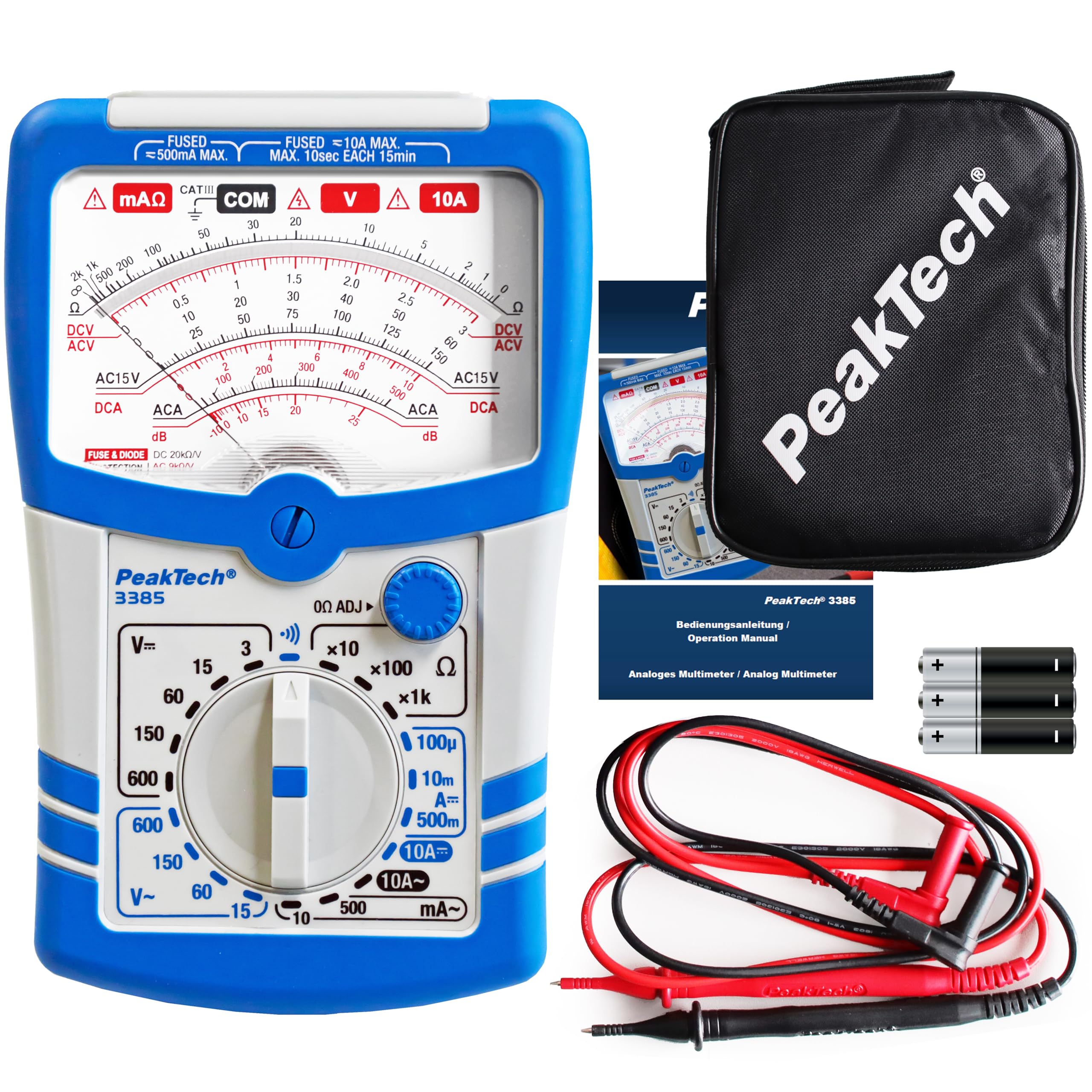
Figure 3.2: Front panel of the PeakTech 3385 multimeter.

Figure 3.3: The versatile function and range selector dial.

Figure 3.4: Detail of the 4mm safety sockets, analog mirror scale, and resistance zero adjustment.
4. Operating Instructions
The PeakTech 3385 offers 20 different measurement ranges. Always select a range higher than the expected value to prevent damage to the meter.
4.1 Measuring DC Voltage (DCV)
- Insert the black test lead into the COM jack and the red test lead into the VΩmA jack.
- Set the function switch to the desired DCV range (e.g., 15V, 60V, 150V, 600V). Start with the highest range if the voltage is unknown.
- Connect the test leads across the component or circuit to be measured.
- Read the voltage value from the appropriate DCV scale on the analog display.
4.2 Measuring AC Voltage (ACV)
- Insert the black test lead into the COM jack and the red test lead into the VΩmA jack.
- Set the function switch to the desired ACV range (e.g., 15V, 60V, 150V, 600V). Start with the highest range if the voltage is unknown.
- Connect the test leads across the component or circuit to be measured.
- Read the voltage value from the appropriate ACV scale on the analog display.
4.3 Measuring DC Current (DCA)
Caution: Always connect the meter in series with the circuit. Never connect it in parallel across a voltage source when measuring current.
- Insert the black test lead into the COM jack.
- For currents up to 500mA, insert the red test lead into the VΩmA jack. For currents up to 10A, insert the red test lead into the 10A jack.
- Set the function switch to the desired DCA range (e.g., 100µA, 10mA, 500mA, 10A).
- Open the circuit where the current is to be measured and connect the meter in series.
- Read the current value from the appropriate DCA scale.
4.4 Measuring Resistance (Ω)
Caution: Ensure the circuit is de-energized and all capacitors are discharged before measuring resistance.
- Insert the black test lead into the COM jack and the red test lead into the VΩmA jack.
- Set the function switch to the desired Ω range (e.g., x1, x10, x100, x1k).
- Short the test leads together. Adjust the Ω ADJ knob until the needle points exactly to zero on the resistance scale.
- Connect the test leads across the component to be measured.
- Read the resistance value from the Ω scale and multiply by the range factor.
4.5 Continuity Test
The continuity test provides an audible indication for low resistance circuits.
- Insert the black test lead into the COM jack and the red test lead into the VΩmA jack.
- Set the function switch to the continuity symbol (often indicated by a speaker icon).
- Connect the test leads across the circuit or component. If continuity exists (low resistance), the meter will emit an audible tone.

Figure 4.1: The PeakTech 3385 is a practical measuring device for various applications.
5. Maintenance
5.1 Cleaning
To clean the meter, wipe the case with a damp cloth and a mild detergent. Do not use abrasives or solvents. Ensure the meter is completely dry before use.
5.2 Battery Replacement
When the meter's display indicates a low battery, or if resistance/continuity functions become unreliable, replace the batteries as described in Section 3.2.
5.3 Fuse Replacement
The PeakTech 3385 is equipped with internal fuses to protect against overcurrent. If the current measurement function stops working, the fuse may need replacement. This procedure should only be performed by qualified personnel.
- Ensure the meter is turned off and all test leads are disconnected.
- Open the battery compartment cover on the back of the meter.
- Carefully remove the old fuse(s). Note the ratings: one for 500mA MAX and another for 10A MAX.
- Replace with fuses of the exact same type and rating. Using incorrect fuses can compromise safety and damage the meter.
- Close the battery compartment cover and secure it.
6. Troubleshooting
If you encounter issues with your PeakTech 3385, refer to the following common problems and solutions:
- No reading or erratic reading:
- Check battery charge and replace if necessary.
- Ensure test leads are properly connected to the meter and the circuit.
- Verify the function switch is set to the correct measurement type and range.
- Inspect test leads for damage or poor connections.
- Resistance/Continuity not working:
- Ensure batteries are fresh and correctly installed.
- Perform the zero adjustment for resistance measurements.
- Confirm the circuit under test is de-energized.
- Current measurement not working:
- Check if the appropriate fuse (500mA or 10A) has blown and replace if needed (refer to Section 5.3).
- Ensure the meter is connected in series with the circuit.
If the problem persists after attempting these solutions, contact PeakTech customer support.
7. Specifications
| Feature | Specification |
|---|---|
| Model Number | P 3385 |
| Dimensions (L x W x H) | 8.9 x 3.4 x 18.3 cm |
| Weight | 380 grams |
| Power Source | 3 x 1.5V AAA Batteries |
| Safety Rating | CAT III 600 V |
| Input Resistance (DC) | 20 kΩ/V |
| Input Resistance (AC) | 9 kΩ/V |
| Measurement Functions | DCV, ACV, DCA, ACA, Resistance, Continuity, dB |
| Measurement Ranges | 20 different ranges |
| Mirror Scale Size | 75 mm |
| Minimum Operating Voltage | 4.5 Volts |
| Upper Rated Temperature | 76 Degrees Celsius |
| Country of Origin | Germany |
| Color | Blue and White |
8. Warranty and Support
8.1 Warranty
The PeakTech 3385 Analog Multimeter comes with a 3-year manufacturer's warranty from the date of purchase. This warranty covers defects in materials and workmanship under normal use. It does not cover damage caused by misuse, accident, unauthorized modification, or neglect.
8.2 Customer Support
For technical assistance, warranty claims, or service inquiries, please contact PeakTech customer support through their official website or the contact information provided with your purchase documentation. Please have your model number (P 3385) and proof of purchase ready when contacting support.


