1. Introduction
This manual provides comprehensive instructions for the installation, operation, and maintenance of the Velleman SV10 6-28V 95dB 2-Mode Buzzer. Please read this manual thoroughly before using the device to ensure proper function and safety.
2. Safety Information
- Ensure the power supply voltage is within the specified operating range (3-28V DC) to prevent damage to the buzzer.
- Always disconnect power before making any connections or performing maintenance.
- Avoid exposing the buzzer to extreme temperatures, moisture, or corrosive environments.
- Do not attempt to disassemble or modify the buzzer, as this may void the warranty and cause malfunction.
- High sound levels can be irritating. Avoid prolonged exposure to the buzzer's sound at close range.
3. Product Overview
The Velleman SV10 is a versatile panel-mounting buzzer designed for various signaling applications. It features fast-on connectors for easy installation and supports two distinct operating modes: continuous and pulse. The buzzer operates within a wide voltage range of 3-28V DC and produces a sound level of approximately 90dB.

Figure 1: Velleman SV10 2-Mode Buzzer. A black, cylindrical buzzer with a ribbed top section and three metal pins extending from the base, designed for panel mounting.
4. Specifications
Refer to the table below for detailed technical specifications of the Velleman SV10 buzzer.
| Specification | Value |
|---|---|
| Model Number | SV10 |
| Operating Voltage | 3-28V DC |
| Rated Voltage | 12V DC |
| Current Consumption | 8mA |
| Sound Level | 90dB (at 12V DC) |
| Oscillation Frequency | 2.9kHz |
| Tone Type | Single / Pulse |
| Connector Type | Faston |
| Mounting Type | Panel-mounting |
| Body Color | Black |
| Weight | 1.2 oz (approx. 34g) |
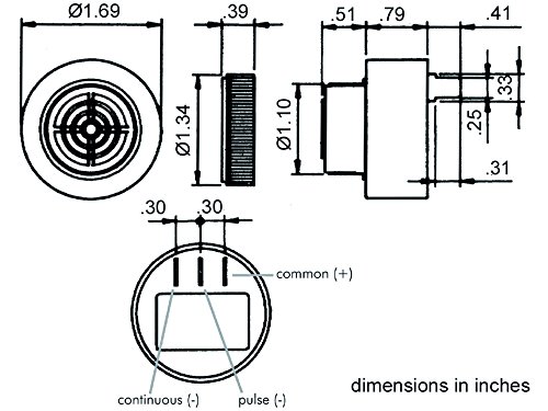
Figure 2: Technical diagram illustrating the dimensions of the Velleman SV10 buzzer in inches, showing top, side, and bottom views, including pin assignments for continuous and pulse modes.
5. Setup and Installation
The Velleman SV10 buzzer is designed for panel mounting and utilizes fast-on connectors for electrical connections. Refer to Figure 2 for pin assignments.
5.1 Pin Identification
- Common (+): This pin is the positive power input for the buzzer.
- Continuous (-): Connecting the negative power supply to this pin will activate the buzzer in a continuous tone mode.
- Pulse (-): Connecting the negative power supply to this pin will activate the buzzer in a pulsating tone mode.
5.2 Wiring Instructions
- Ensure the power supply is turned off before making any connections.
- Connect the positive (+) terminal of your DC power supply (3-28V DC) to the Common (+) pin of the buzzer using a fast-on connector.
- To achieve a continuous tone, connect the negative (-) terminal of your DC power supply to the Continuous (-) pin of the buzzer.
- To achieve a pulsating tone, connect the negative (-) terminal of your DC power supply to the Pulse (-) pin of the buzzer.
- Only connect one negative terminal (either Continuous or Pulse) at a time. Connecting both simultaneously is not recommended and may result in unpredictable behavior.
- Securely mount the buzzer into a suitable panel cutout.
6. Operating Instructions
Once properly installed and wired according to Section 5, the Velleman SV10 buzzer will activate when power is supplied to the selected mode pin.
- Continuous Mode: When the negative supply is connected to the 'Continuous (-)' pin, the buzzer will emit a steady, uninterrupted tone.
- Pulse Mode: When the negative supply is connected to the 'Pulse (-)' pin, the buzzer will emit a repetitive, on-off pulsating tone.
The sound level and frequency are fixed as per the specifications. The buzzer will remain active as long as the appropriate power is supplied.
7. Maintenance
The Velleman SV10 buzzer is designed for low maintenance. Follow these guidelines to ensure its longevity:
- Keep the buzzer clean and free from dust and debris. Use a soft, dry cloth for cleaning.
- Do not use harsh chemicals or abrasive cleaners.
- Regularly inspect the wiring connections to ensure they are secure and free from corrosion.
- Ensure the operating environment remains within the specified temperature and humidity ranges.
8. Troubleshooting
If the buzzer is not functioning as expected, consider the following troubleshooting steps:
- No Sound:
- Verify that the power supply is connected and providing the correct voltage (3-28V DC).
- Check all wiring connections for looseness or incorrect polarity. Ensure the positive supply is on the Common (+) pin and the negative supply is on either the Continuous (-) or Pulse (-) pin.
- Confirm that only one negative pin (Continuous or Pulse) is connected at a time.
- Incorrect Tone (Continuous instead of Pulse, or vice-versa):
- Recheck the negative (-) wiring to ensure it is connected to the desired mode pin (Continuous or Pulse).
- Weak or Distorted Sound:
- Ensure the power supply voltage is stable and within the operating range. Low voltage can affect sound output.
- Check for any obstructions around the buzzer's sound outlet.
If problems persist after following these steps, contact Velleman support or a qualified technician.
9. Disposal Information
This product should not be disposed of with household waste. Please recycle it at designated collection points for electronic waste. Proper disposal helps prevent potential negative consequences for the environment and human health.


