
1. Introduction
This manual provides detailed instructions for the installation, operation, and maintenance of the Dwyer MS Magnesense Differential Pressure Transmitter, Model MS-321-LCD. This device is designed for accurate measurement of differential pressure in various industrial and scientific applications, featuring a clear LCD for direct readings.
2. Safety Information
Read this manual thoroughly before installing or operating the MS-321-LCD transmitter. Failure to follow these instructions may result in product damage, property damage, or personal injury. Keep this manual for future reference.
- Ensure power is disconnected before installation or maintenance.
- Installation should only be performed by qualified personnel.
- Do not exceed the specified pressure or electrical ratings.
- Protect the device from extreme temperatures, moisture, and corrosive environments unless specifically rated for such conditions.
3. Setup and Installation
3.1 Mounting
The MS-321-LCD transmitter is designed for surface or duct mounting. Ensure the mounting location is free from excessive vibration and within the specified operating temperature range.
- Select a suitable flat surface or duct wall for mounting.
- Use appropriate screws (not supplied) to secure the mounting tabs of the transmitter to the chosen surface.
- Ensure the device is mounted securely to prevent movement.
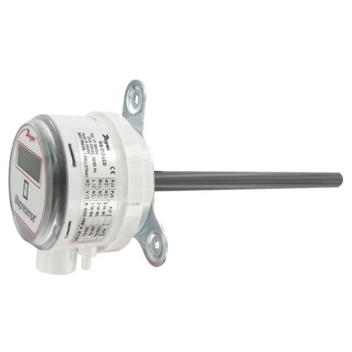
Side view of the Dwyer MS Magnesense Differential Pressure Transmitter, illustrating the mounting tabs, pressure sensing ports, and the side label with technical specifications.
3.2 Pressure Connections
Connect the pressure tubing to the appropriate ports on the transmitter. The MS-321-LCD typically has two ports for differential pressure measurement: a high-pressure port and a low-pressure port.
- Connect the higher pressure source to the '+' port.
- Connect the lower pressure source to the '-' port.
- Ensure all connections are airtight to prevent leaks and ensure accurate readings.
3.3 Electrical Wiring
The MS-321-LCD requires a power supply and provides an analog output signal. Refer to the wiring diagram on the device label or in the full technical datasheet for specific connections.
- Power Supply: Connect the appropriate DC voltage (e.g., 10-35 VDC) to the power terminals. Observe polarity.
- Output Signal: The device provides a 0-10 V output signal. Connect the output terminals to your control system or data acquisition device.
- Ensure all electrical connections comply with local electrical codes.
3.4 Range Selection
The MS-321-LCD model allows for selectable pressure ranges. The available ranges are typically 0.1", 0.25", and 0.5" Water Column (W.C.), or their metric equivalents (25, 50, 100 Pa). Consult the device's internal jumpers or dip switches for range configuration. (Specific instructions for range selection are typically found on the device's internal PCB or a separate quick start guide. Refer to the manufacturer's full technical documentation for precise steps.)
4. Operating Instructions
Once installed and powered, the MS-321-LCD will begin measuring differential pressure. The current reading is displayed on the integrated LCD.
- LCD Display: The LCD shows the measured differential pressure in the selected engineering units (e.g., IN WC or Pa).
- Zero Function: Some models may include a zero adjustment button or function. If present, ensure the pressure ports are open to atmosphere (or at equal pressure) before performing a zero adjustment to ensure accurate baseline readings.
- Analog Output: The 0-10 V output signal corresponds linearly to the selected pressure range. For example, if the range is 0-0.5" W.C., then 0 V = 0" W.C. and 10 V = 0.5" W.C.
5. Maintenance
The Dwyer MS-321-LCD is designed for long-term, reliable operation with minimal maintenance.
- Cleaning: Periodically clean the exterior of the device with a soft, damp cloth. Do not use abrasive cleaners or solvents.
- Pressure Ports: Ensure pressure ports remain clear of debris.
- Recalibration: While factory calibrated, periodic recalibration may be required depending on application and regulatory requirements. Refer to the manufacturer's full technical documentation for calibration procedures.
6. Troubleshooting
If the device is not functioning as expected, consider the following common issues:
| Problem | Possible Cause | Solution |
|---|---|---|
| No display/No power | Incorrect wiring, no power supply, faulty power supply. | Check power connections and voltage. Verify power supply functionality. |
| Inaccurate readings | Leaking pressure connections, incorrect range selection, sensor blockage, need for zero adjustment. | Check all pressure tubing for leaks. Verify correct range setting. Clear pressure ports. Perform zero adjustment if applicable. |
| No analog output | Incorrect wiring, faulty output connection, device malfunction. | Verify output wiring to control system. Check for continuity. |
If problems persist, contact Dwyer Instruments technical support.
7. Specifications
- Model: MS-321-LCD
- Brand: Dwyer Instruments
- Pressure Ranges (Selectable): 0.1", 0.25", 0.5" W.C. (Water Column) or 25, 50, 100 Pa (Pascals)
- Output: 0-10 VDC
- Enclosure Rating: IP65
- Manufacturer: Dwyer Instruments, Inc.
- ASIN: B00GJVV4YA
- First Available: November 2, 2014
8. Warranty and Support
Dwyer Instruments products are typically covered by a limited warranty against defects in materials and workmanship. For specific warranty terms and conditions, please refer to the official Dwyer Instruments website or contact their customer service.
For technical assistance, troubleshooting, or to inquire about repairs, please contact Dwyer Instruments directly through their official support channels.
Manufacturer: Dwyer Instruments, Inc.
Website: www.dwyer-inst.com


