1. Introduction
This manual provides essential information for the installation, programming, and operation of your Electrodepot 93EL6DR Smart PLC Programmable Mini Controller. This device is designed for various automation tasks, offering robust control capabilities in a compact form factor.
The 93EL6DR features 8 DC inputs (including 2 analog 0-10V inputs), 4 relay outputs, an integrated HMI display, and a keypad for direct programming. It supports ladder logic programming and includes a real-time clock for time-based operations.
2. Safety Information
Please read and understand all safety instructions before installing, operating, or maintaining the controller. Failure to follow these instructions may result in personal injury or equipment damage.
- Electrical Safety: Ensure power is disconnected before making any wiring connections. All wiring should be performed by qualified personnel in accordance with local electrical codes.
- Voltage: The controller operates on 24VDC. Verify correct voltage supply to prevent damage. Relay outputs can handle up to 250V, 10A.
- Environment: Install the controller in a clean, dry environment, free from excessive dust, moisture, and corrosive gases.
- Mounting: Securely mount the device on a DIN rail to prevent accidental dislodgement.
3. Product Overview
The Electrodepot 93EL6DR is a compact programmable logic controller designed for ease of use and versatility. It integrates a display and keypad for on-device interaction and programming.

Image 3.1: Front view of the Electrodepot Smart PLC Mini Controller, showing the integrated display and keypad for user interaction and programming.
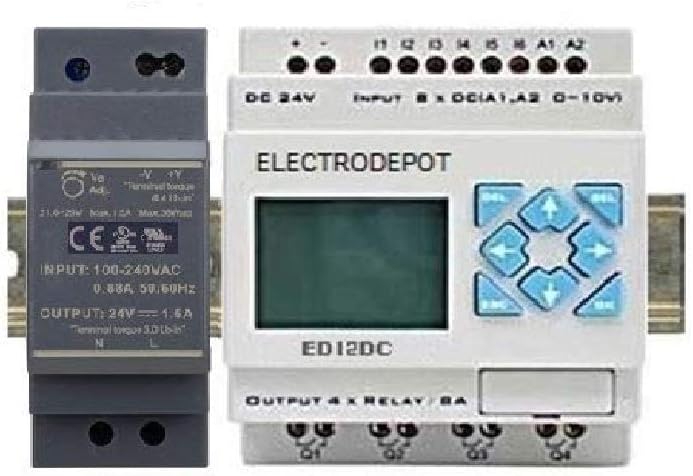
Image 3.2: The Electrodepot Smart PLC Mini Controller shown alongside a compatible 24VDC power supply unit, both designed for DIN rail mounting.
3.1. Components
- HMI Display: Liquid Crystal Display for status monitoring and programming.
- Keypad: Navigation and input buttons for on-device programming and control.
- Input Terminals: 8 DC inputs (I1-I8), including 2 analog inputs (A1, A2) for 0-10V signals.
- Output Terminals: 4 Relay outputs (Q1-Q4) for controlling external devices.
- Power Terminals: DC 24V input for power supply.
- USB Port: For PC connection to upload/download programs and monitor status.
4. Setup
4.1. Mounting
The 93EL6DR controller is designed for DIN rail mounting. Snap the unit onto a standard 35mm DIN rail in your control panel. Ensure adequate ventilation around the unit.
4.2. Wiring
Carefully follow the wiring diagram for connecting power, inputs, and outputs. Ensure all connections are secure to prevent intermittent operation or damage.
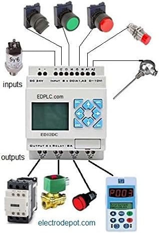
Image 4.1: A comprehensive wiring diagram illustrating how various input devices (e.g., sensors, push buttons) and output devices (e.g., contactors, solenoid valves) are connected to the Electrodepot PLC.
- Power Supply: Connect a stable 24VDC power source to the DC 24V terminals. Observe polarity (+ and -).
- DC Inputs (I1-I8): Connect your digital input devices (e.g., switches, proximity sensors) to these terminals.
- Analog Inputs (A1, A2): These inputs accept 0-10V analog signals from sensors (e.g., temperature, pressure).
- Relay Outputs (Q1-Q4): Connect the devices you wish to control (e.g., motors, lights, valves) to these relay contacts. Each relay can switch up to 10A at 250V.
5. Software Installation & Programming
The Electrodepot 93EL6DR can be programmed directly via its HMI and keypad or through PC software using a USB connection.
5.1. PC Software Programming (Ladder Logic)
Install the provided programming software on your computer. This software allows you to create and edit ladder logic programs, simulate their operation, and then upload them to the PLC via the USB interface.

Image 5.1: A screenshot displaying the Ladder Logic programming environment, where users can design and implement control sequences for the PLC.
5.2. Real-time Clock (RTC) Setup
The integrated real-time clock allows for time-based control functions. The RTC can be configured via the PC software or directly through the PLC's keypad and display.

Image 5.2: Screenshot of the Real-time Clock (RTC) settings interface, enabling precise scheduling of operations based on time and date.
6. Operation
Once programmed, the PLC will execute the loaded logic. The HMI display provides status information, and the keypad can be used for basic monitoring, parameter adjustments, or manual control depending on the program.
- Monitoring: Use the display to view input/output status, timer/counter values, and program execution.
- Keypad Navigation: Use the arrow keys to navigate menus and the OK/ESC buttons for selection and exit.
- Program Execution: The PLC operates continuously once powered and a program is loaded.
7. Applications
The Electrodepot 93EL6DR is suitable for a wide range of automation tasks, from simple control sequences to more complex industrial processes.

Image 7.1: An example application diagram showing the PLC used in a greenhouse automation system, integrating a solar panel, moisture sensors, temperature sensors, and controlling heat, ventilation, and water pumps.
Common applications include:
- Industrial process control (e.g., packing, conveyors, transportation)
- Home automation systems
- Security systems
- Lighting and climate control
8. Maintenance
Regular maintenance helps ensure the longevity and reliable operation of your PLC controller.
- Cleaning: Keep the unit free from dust and debris. Use a soft, dry cloth for cleaning. Do not use liquid cleaners.
- Connections: Periodically check all wiring connections for tightness and signs of corrosion.
- Environment: Ensure the operating environment remains within specified temperature and humidity ranges.
9. Troubleshooting
If you encounter issues with your Electrodepot 93EL6DR, consider the following common troubleshooting steps:
- No Power: Verify the 24VDC power supply is connected correctly and is active. Check fuses if applicable.
- Inputs Not Responding: Check wiring to input devices. Ensure input signals are within the specified voltage range. Verify the program logic for input handling.
- Outputs Not Activating: Check wiring to output devices. Ensure external devices are powered. Verify the program logic for output control.
- Communication Issues (PC): Ensure USB drivers are correctly installed. Check USB cable connection.
- Incorrect Program Behavior: Review your ladder logic program for errors. Use the simulation feature in the PC software to debug.
For persistent issues, contact Electrodepot technical support.
10. Specifications
| Feature | Specification |
|---|---|
| Model Number | 93EL6DR |
| Brand | Electrodepot |
| Input Voltage | 24VDC |
| Digital Inputs | 8 (DC) |
| Analog Inputs | 2 (0-10V) |
| Output Type | Relay (N/O) |
| Relay Outputs | 4 |
| Relay Output Rating | 10A @ 250V |
| Programming Method | Ladder Logic (PC software or Keypad) |
| Display | HMI Display |
| Clock Function | 365 Days Real-time Clock |
| Mounting | DIN Rail |
| Dimensions (LxWxH) | 1.89 x 2.52 x 3.54 inches |
| Weight | 3 ounces |
11. Warranty and Support
Electrodepot products are manufactured to high-quality standards. For warranty information and technical support, please refer to the documentation included with your purchase or visit the official Electrodepot website. Keep your purchase receipt as proof of purchase.


