1. Introduction
The Juniper Networks EX4300-48P Ethernet PoE Switch is designed to provide a high-performance, scalable solution for data center, campus, and branch office environments. This switch combines carrier-class reliability with the flexibility of stackable platforms, offering a full suite of Layer 2 and Layer 3 switching capabilities. It supports Power over Ethernet (PoE) for connecting and powering compatible devices, and features Virtual Chassis technology for interconnecting multiple switches into a single logical device.
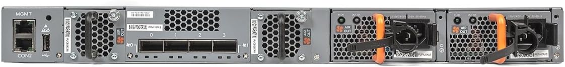
Figure 1: Angled view of the Juniper Networks EX4300-48P Ethernet PoE Switch, showcasing its robust metal casing and port layout.
2. Safety Information
Observe the following safety precautions to prevent injury and damage to the equipment:
- Ensure proper grounding of the switch before connecting power.
- Do not operate the switch in environments exceeding the specified temperature and humidity ranges.
- Avoid blocking ventilation openings to prevent overheating.
- Use only the power supply provided or approved by Juniper Networks.
- Do not attempt to service the switch yourself. Refer all servicing to qualified personnel.
- Keep liquids away from the switch to prevent electrical shock or damage.
3. Package Contents
Verify that your package contains the following items. If any item is missing or damaged, contact your vendor.
- Juniper Networks EX4300-48P Ethernet PoE Switch
- Power cord
- Rack-mount kit (if applicable)
- Console cable
- Documentation (Quick Start Guide, Safety Information)
4. Setup
4.1 Physical Installation
The EX4300-48P switch can be installed in a standard 19-inch equipment rack or placed on a desktop. Ensure adequate airflow around the unit.
- Rack-Mounting: Attach the provided rack-mount brackets to the sides of the switch and secure it into the rack using appropriate screws.
- Desktop Placement: Ensure the surface is flat, stable, and allows for proper ventilation.
4.2 Front Panel Overview

Figure 2: Front panel of the EX4300-48P switch, showing 48 PoE+ Ethernet ports and uplink module slots.
The front panel features 48 Gigabit Ethernet ports with Power over Ethernet Plus (PoE+), allowing connection and power delivery to devices such as IP phones, wireless access points, and surveillance cameras. It also includes slots for optional uplink modules, providing flexible high-speed connectivity options.
4.3 Rear Panel Overview

Figure 3: Rear panel of the EX4300-48P switch, displaying power supply bays, fan modules, and management ports.
The rear panel houses the power supply bays, fan modules for cooling, and various management interfaces including a console port and an out-of-band management Ethernet port (MGMT). It also contains the Virtual Chassis ports (QSFP+) for interconnecting multiple EX4300 switches.
4.4 Connecting Power
- Ensure the power switch (if present) is in the OFF position.
- Connect the power cord to the AC power inlet on the rear panel of the switch.
- Plug the other end of the power cord into a grounded electrical outlet.
- Turn the power switch to the ON position. The system status LEDs should illuminate.
4.5 Initial Configuration Access
Initial configuration can be performed via the console port or the dedicated management Ethernet port.
- Console Port: Connect a console cable from your management workstation to the console port on the switch. Use a terminal emulation program (e.g., PuTTY, Tera Term) with settings: 9600 baud, 8 data bits, no parity, 1 stop bit, no flow control.
- Management Port (MGMT): Connect an Ethernet cable from your management workstation to the MGMT port. Configure your workstation's IP address to be on the same subnet as the switch's default management IP (refer to the Quick Start Guide for default IP).
5. Operating the Switch
5.1 Basic Operation
Once powered on and initially configured, the EX4300-48P switch begins forwarding traffic according to its default or configured settings. The switch operates as a Layer 2 device by default, performing MAC address learning and forwarding frames based on destination MAC addresses. Layer 3 routing capabilities can be enabled and configured for inter-VLAN routing and other advanced network functions.
5.2 Power over Ethernet (PoE)
The EX4300-48P provides Power over Ethernet (PoE) on its 48 access ports. This feature allows the switch to deliver electrical power along with data to connected devices over standard Ethernet cabling. Ensure that connected devices are PoE-compatible and do not exceed the switch's total power budget. PoE status can be monitored via the command-line interface (CLI) or network management system.
5.3 Virtual Chassis Technology
Juniper Networks Virtual Chassis technology allows up to 10 EX4300 switches to be interconnected and managed as a single logical device. This provides a scalable, pay-as-you-grow solution for expanding network environments. Switches are interconnected using the 40GbE QSFP+ transceiver ports on the rear panel. Configuration and management of the Virtual Chassis are performed from the master switch.
6. Maintenance
6.1 Cleaning
- Periodically clean the exterior of the switch with a soft, dry, lint-free cloth.
- Ensure ventilation openings are free from dust and debris to maintain proper cooling.
- Do not use liquid or aerosol cleaners directly on the switch.
6.2 Firmware Updates
Regularly check the Juniper Networks support website for the latest firmware updates. Keeping the switch firmware up-to-date ensures optimal performance, security, and access to new features. Follow the instructions provided with the firmware release for the update procedure.
6.3 Environmental Considerations
Maintain the operating environment within the specified temperature and humidity ranges to ensure the longevity and reliable operation of the switch. Avoid exposing the switch to direct sunlight, excessive heat, or moisture.
7. Troubleshooting
7.1 No Power
- Verify the power cord is securely connected to both the switch and the electrical outlet.
- Check if the power outlet is functional by plugging in another device.
- Ensure the power switch on the rear panel is in the ON position.
- Inspect the power supply unit for any visible damage or fault indicators.
7.2 No Network Connectivity
- Check the link/activity LEDs on the connected ports. If off, verify the cable connection and the status of the connected device.
- Ensure the correct VLANs and IP configurations are applied to the switch interfaces and connected devices.
- Verify that the switch ports are not administratively shut down.
- Test with a different Ethernet cable or port.
7.3 PoE Not Functioning
- Confirm that the connected device is PoE-compatible.
- Check the PoE status LEDs on the front panel for the specific port.
- Verify the switch's total PoE power budget and ensure it is not exceeded.
- Use the CLI to check PoE port status and power allocation.
7.4 System Status LEDs
Refer to the product documentation for a detailed explanation of the system status LEDs (e.g., SYS, ALM, RPS, PoE) and their indications. These LEDs provide quick visual diagnostics of the switch's operational state and any potential issues.
8. Specifications
| Feature | Description |
|---|---|
| Brand | Juniper Networks |
| Model Number | EX4300-48P |
| Number of Ports | 48 |
| Switch Type | Layer 3 |
| Number of Layers | 3 |
| Interface | PoE |
| Data Transfer Rate | 320 Gigabits Per Second |
| Compatible Devices | Desktop |
| Item Weight | 7300 Grams |
| Voltage | 48 Volts (DC) |
| Upper Temperature Rating | 40 Degrees Celsius |
| Case Material Type | Metal |
| Color | Grey |
| UPC | 832938063549 |
| GTIN | 832938063549 |


