1. Introduction
This manual provides essential information for the proper installation, operation, and maintenance of the VEMER VM625100 HT NiPt-1P7A Digital Panel Thermoregulator. Please read this manual thoroughly before using the device to ensure safe and efficient operation.
2. Product Overview
The VEMER VM625100 HT NiPt-1P7A is a digital panel-mounted thermoregulator designed for precise temperature control in various applications, including ovens, refrigerated counters, and ambient temperature regulation. It supports both heating and cooling modes. The device features two inputs for Ni100 and Pt100 thermoresistance probes, one for regulation and one for display, and includes a single output relay. An acoustic and visual alarm system alerts users to minimum/maximum temperature deviations or probe malfunctions. The bright red LED display ensures clear readability of measurements.
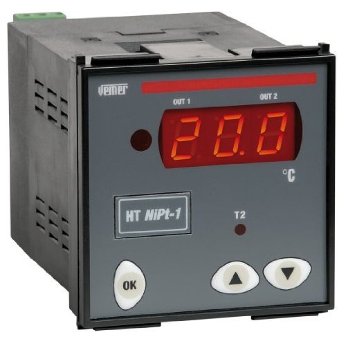
Front view of the VEMER VM625100 digital panel thermoregulator, showing its gray casing, red LED display indicating '20.0', and control buttons labeled 'OK', 'Up arrow', and 'Down arrow'. The VEMER logo is visible at the top left.
3. Safety Information
- Ensure all electrical connections are made by qualified personnel in accordance with local and national electrical codes.
- Disconnect power before performing any installation, wiring, or maintenance procedures.
- Do not expose the device to moisture, extreme temperatures, or corrosive environments.
- Verify the power supply voltage matches the device's specifications (24/230V).
- Do not attempt to open or repair the device. Refer servicing to authorized personnel.
4. Installation
4.1 Panel Mounting
The VM625100 is designed for panel mounting with dimensions of 72x72 mm. Create an appropriate cutout in the panel according to the device's specifications. Insert the thermoregulator into the cutout and secure it using the provided mounting clips.
4.2 Electrical Connections
The device operates on a 24/230V power supply. Connect the power input terminals as indicated in the detailed wiring diagram found in the complete product manual. Connect the thermoresistance probes (Ni100 or Pt100) to the designated input terminals. Connect the output relay to the controlled load (e.g., heater, cooler) according to the application requirements. Ensure all connections are secure and correctly polarized.
5. Operation
5.1 Power On
Once properly installed and wired, apply power to the device. The red LED display will illuminate, showing the current temperature reading from the primary probe.
5.2 Setting Temperature
Use the 'Up' and 'Down' arrow buttons to adjust the desired setpoint temperature. Press the 'OK' button to confirm the setting. Refer to the full manual for specific menu navigation and parameter adjustments.
5.3 Alarm Functions
The thermoregulator features acoustic and visual alarms for minimum and maximum temperature thresholds, as well as for probe malfunctions. When an alarm condition is met, the device will activate an audible signal and display a visual indicator. Consult the detailed manual for alarm configuration and acknowledgment procedures.
5.4 Password Protection
The device includes a password protection feature to prevent unauthorized changes to settings. This function can be enabled and configured through the device's menu. Refer to the complete manual for instructions on setting and using the password.
6. Maintenance
The VEMER VM625100 thermoregulator requires minimal maintenance. Keep the device clean and free from dust. Use a soft, dry cloth for cleaning. Do not use abrasive cleaners or solvents. Regular inspection of wiring connections for tightness and integrity is recommended. There are no user-serviceable parts inside the unit.
7. Troubleshooting
- Device not powering on: Check power supply connections and voltage. Ensure the power source is active.
- Incorrect temperature reading: Verify probe connections. Ensure the correct probe type (Ni100/Pt100) is selected in the settings and that the probe is functioning correctly.
- Alarm continuously active: Check setpoint and alarm threshold settings. Inspect the probe for damage or disconnection. Ensure the controlled environment is within the desired temperature range.
- Output relay not activating: Check wiring to the load. Verify setpoint and current temperature. Ensure the operating mode (heating/cooling) is correctly configured.
For persistent issues, consult the comprehensive product manual or contact VEMER technical support.
8. Technical Specifications
| Specification | Value |
|---|---|
| Manufacturer | VEMER |
| Model Number | VM625100 |
| Panel Dimensions | 72x72 mm |
| Power Supply | 24/230V |
| Probe Inputs | 2 (Ni100, Pt100 thermoresistance) |
| Output Relay | 1 |
| Measurement Accuracy | ± 0.5% |
| Display Type | LED (Red) |
| Special Functions | Alarm, Password Protection |
| Included Components | Product, User Manual |
| Color | Gray |
| Weight | 445 g |
| Package Dimensions | 15.5 x 11 x 10.8 cm |
9. Warranty and Support
The VEMER VM625100 HT NiPt-1P7A Digital Panel Thermoregulator is covered by the manufacturer's standard warranty. For detailed warranty terms and conditions, please refer to the documentation included with your product or visit the official VEMER website. For technical assistance, troubleshooting beyond this manual, or spare parts, please contact VEMER customer support.


