1. Introduction
This manual provides essential information for the safe and effective use of the Keyence AP-34KP Pressure Sensor. Please read this manual thoroughly before operating the device and keep it for future reference.
The Keyence AP-34KP is a high-precision pressure sensor designed for industrial applications, offering reliable measurement and control capabilities.
2. Safety Information
WARNING:
- Always disconnect power before performing any installation, wiring, or maintenance.
- Ensure proper grounding to prevent electric shock.
- Do not exceed the specified pressure range or electrical ratings.
- Only qualified personnel should perform installation and maintenance.
- Avoid exposing the sensor to corrosive gases or liquids unless specifically rated for such environments.
3. Product Overview
The AP-34KP Pressure Sensor features a compact design with an integrated display and control buttons for easy operation and monitoring.

Figure 3.1: Front view of the Keyence AP-34KP Pressure Sensor. This image displays the main body of the sensor, featuring a digital display, and control buttons labeled 'A', 'OUT1', and 'OUT2', along with up and down arrow buttons.
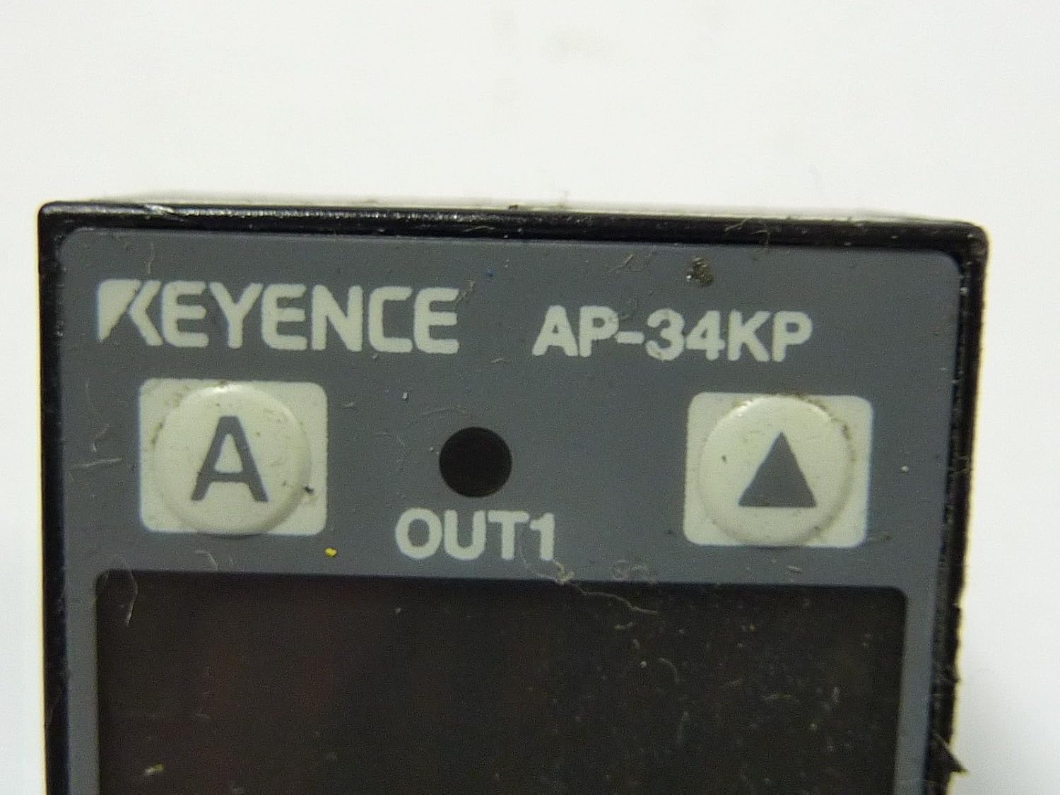
Figure 3.2: Close-up of the sensor's control panel. This detailed view highlights the 'KEYENCE AP-34KP' branding, the 'A' button for mode selection, the 'OUT1' indicator, and the up and down arrow buttons for value adjustment. The 'OUT2' button is also visible.

Figure 3.3: Rear view of the sensor. This image shows the back of the AP-34KP, revealing the threaded pressure port for connection to the pressure source and the integrated electrical cable for power and signal output.
4. Setup and Installation
4.1 Mounting
The AP-34KP can be mounted using standard brackets or directly integrated into a system. Ensure the mounting location is stable and free from excessive vibration.
- Select a mounting position that allows for easy access to the display and buttons.
- Securely fasten the sensor using appropriate screws or clamps.
- Ensure the pressure port is clean and free of debris before connection.
4.2 Pressure Connection
Connect the pressure source to the sensor's threaded port (refer to Figure 3.3). Use appropriate sealing tape or compound to ensure a leak-free connection.
- Apply thread sealant to the pressure fitting.
- Carefully thread the fitting into the sensor's pressure port.
- Tighten to the recommended torque, avoiding overtightening.
4.3 Electrical Wiring
Connect the sensor to the power supply and control system according to the wiring diagram provided in your system's documentation. The sensor typically requires a DC power supply.
- Identify the power input, ground, and output signal wires.
- Connect wires to the appropriate terminals, ensuring correct polarity.
- Verify all connections are secure before applying power.
5. Operating Instructions
5.1 Power On
Once wired, apply power to the sensor. The display will illuminate and show the current pressure reading.
5.2 Basic Operation
- Display: Shows the real-time pressure value.
- 'A' Button: Used to cycle through different display modes or enter programming mode.
- Up/Down Arrows: Adjust set points or navigate menu options in programming mode.
- 'OUT1' / 'OUT2' Buttons: Typically used to select or confirm output settings or parameters.
5.3 Setting Parameters (Example)
To set an output threshold:
- Press the 'A' button to enter programming mode.
- Use the Up/Down arrows to navigate to the desired parameter (e.g., OUT1 set point).
- Press 'OUT1' or 'A' again to select the parameter for editing.
- Use the Up/Down arrows to adjust the value.
- Press 'A' or 'OUT1' to confirm the setting and exit the parameter editing.
- Continue pressing 'A' to exit programming mode and return to normal operation.
6. Maintenance
The Keyence AP-34KP Pressure Sensor is designed for minimal maintenance. However, regular checks can ensure optimal performance and longevity.
- Cleaning: Gently wipe the sensor's exterior with a soft, damp cloth. Do not use abrasive cleaners or solvents.
- Pressure Port: Periodically check the pressure port for any blockages or debris. Ensure the connection remains leak-free.
- Cable Integrity: Inspect the electrical cable for any signs of damage, fraying, or wear.
- Calibration: While factory calibrated, if precise measurements are critical and drift is suspected, consult Keyence for re-calibration services.
7. Troubleshooting
| Problem | Possible Cause | Solution |
|---|---|---|
| No display/No power | No power supply; Incorrect wiring; Blown fuse. | Check power connections; Verify wiring diagram; Replace fuse if necessary. |
| Incorrect pressure reading | Pressure port blocked; Sensor not calibrated; Leak in pressure line. | Clear blockage; Consider re-calibration; Check for leaks and seal connections. |
| Output not switching | Set point incorrect; Wiring error; Sensor fault. | Verify set point in programming mode; Check output wiring; Contact support if fault persists. |
| Display shows error code | Internal sensor error; Out of range pressure. | Refer to Keyence's specific error code documentation (not provided here); Ensure pressure is within operating range. |
8. Specifications
- Model: AP-34KP
- Manufacturer: Keyence
- ASIN: B00F1MTQIO
- Package Dimensions: 6.02 x 4.45 x 1.81 inches
- Weight: Approximately 6 ounces
- Note: For detailed electrical, pressure range, and environmental specifications, please refer to the official Keyence AP-34KP datasheet.
9. Warranty Information
Keyence products are typically covered by a limited warranty against defects in materials and workmanship. The specific terms and duration of the warranty may vary by region and product. Please refer to the official warranty statement provided with your purchase or visit the Keyence official website for detailed warranty information.
Retain your proof of purchase for warranty claims.
10. Customer Support
For technical assistance, troubleshooting beyond this manual, or service inquiries, please contact Keyence customer support.
- Keyence Official Website: www.keyence.com
- Contact Information: Refer to the "Contact Us" section on the official website for regional phone numbers and email support.


