
Johnson Controls M9108-GGC-2
Johnson Controls M9108-GGC-2 Electric Non-Spring-Return Actuator User Manual
Model: M9108-GGC-2
1. Introduction
This manual provides essential information for the safe and efficient installation, operation, and maintenance of the Johnson Controls M9108-GGC-2 Electric Non-Spring-Return Actuator. The M9108-GGC-2 is part of the M91xx series of direct-mount electric actuators, designed for use with on/off, floating, proportional, or resistive controllers. It operates on AC/DC 24 V power and delivers 8 Nm (70 in-lb) of torque. This actuator is suitable for direct mounting on dampers with round shafts up to 3/4 inch (20 mm) or square shafts up to 5/8 inch (16 mm), or can be used with M9000-5xx Valve Linkage Kits for valve applications. It features mechanically adjustable rotation from 0 to 90 degrees in 5-degree increments and includes 2-SPDT auxiliary switches for position indication or switching functions.
2. Safety Information
Read and understand all instructions before installing or operating this product. Failure to follow these instructions may result in product damage, property damage, or personal injury. Installation and servicing must be performed by qualified personnel in accordance with all applicable codes and regulations.
- Disconnect all power to the actuator and controlled equipment before installation or servicing to prevent electrical shock or equipment damage.
- Ensure proper grounding of the actuator.
- Do not exceed the specified voltage and current ratings.
- Protect the actuator from moisture and extreme temperatures beyond its operating range.
- Verify all wiring connections are secure and correct before applying power.
3. Product Overview
The Johnson Controls M9108-GGC-2 actuator is designed for reliable and precise control in various applications. Its direct coupling design simplifies installation and enhances reliability by eliminating the need for external damper linkages. The actuator incorporates electronic stall detection, which deactivates the motor if a stall condition is detected, ensuring higher reliability and preventing damage.
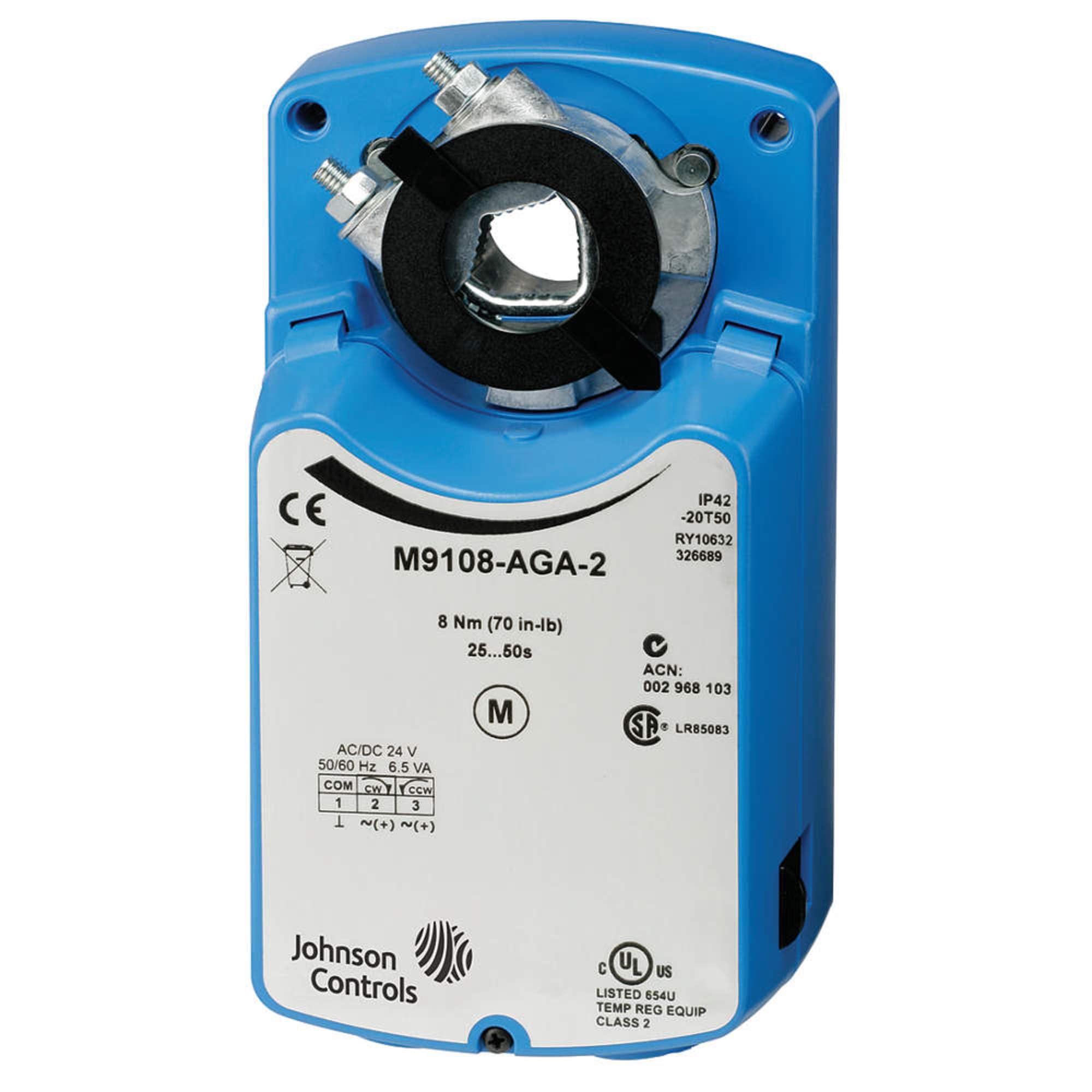
Figure 1: Johnson Controls M9108-GGC-2 Electric Non-Spring-Return Actuator. This image displays the blue actuator unit, highlighting its direct-mount shaft connection. Visible labels indicate a model variant (M9108-AGA-2), 8 Nm (70 in-lb) torque, 25-50 second rotation time, AC/DC 24V power input, IP42 protection rating, and Johnson Controls branding along with various certifications.
Key Features:
- Direct Coupling: Reduces installation time and improves reliability.
- Multiple Control Inputs: Compatible with on/off, floating, proportional, or resistive controllers.
- Output Position Feedback: Provides accurate position sensing for closed-loop control.
- Electronic Stall Detection: Enhances reliability by protecting the motor from stall conditions.
- NPT Threaded Housing: Facilitates easy connection for electrical fittings.
- Auxiliary Switches: Two SPDT switches for end-stop indication or other switching functions.
4. Setup and Installation
Proper installation is crucial for the actuator's performance and longevity. Ensure all local and national electrical codes are followed.
4.1 Mounting
- Damper Mounting: The actuator can be directly mounted to a damper with a round shaft up to 3/4 inch (20 mm) in diameter or a square shaft up to 5/8 inch (16 mm). Ensure the shaft is clean and free of burrs.
- Valve Mounting: For valve applications, use one of the M9000-5xx Valve Linkage Kits (sold separately). Refer to the specific linkage kit instructions for detailed mounting procedures.
- Orientation: Mount the actuator in an orientation that allows for easy access to wiring and adjustments, and ensures proper drainage if exposed to moisture.
4.2 Wiring
The M9108-GGC-2 operates on AC/DC 24 V power. The NPT threaded housing provides a secure connection for electrical conduits. Refer to the wiring diagram provided with your specific actuator model for detailed connection instructions. Ensure all connections are tight and insulated.
- Power Supply: Connect the AC/DC 24 V power supply to the designated terminals.
- Control Input: Connect the control signal (on/off, floating, proportional, or resistive) to the appropriate terminals. The M9108-GGC-2 supports DC 0(2) to 10 V control signals.
- Auxiliary Switches: The 2-SPDT auxiliary switches can be wired to external systems for position indication or to perform switching functions at specific angles of rotation.
- Position Feedback: If using position feedback, connect the output signal (DC 0(2) to 10 V) to the receiving controller or monitoring system.
5. Operating Instructions
Once installed and wired, the actuator is ready for operation. The M9108-GGC-2 is a non-spring-return actuator, meaning it will maintain its last position upon power loss.
5.1 Angle of Rotation Adjustment
The angle of rotation can be mechanically adjusted from 0 to 90 degrees in 5-degree increments. This adjustment is typically performed using mechanical stops on the actuator or the damper/valve assembly. Consult the actuator's specific product sheet for detailed instructions on setting the rotation limits.
5.2 Control Modes
The actuator responds to various control signals:
- On/Off Control: The actuator moves to one end position when power is applied and to the other when power is removed or a specific signal is present.
- Floating Control: The actuator moves in one direction when one control signal is active and in the opposite direction when another is active, stopping when neither is active.
- Proportional Control (DC 0(2) to 10 V): The actuator's position is proportional to the input control signal. A 0(2) to 10 V DC signal typically corresponds to a 0 to 100% rotation.
- Resistive Control: The actuator's position is determined by a resistive input signal.
5.3 Auxiliary Switches
The integral auxiliary switches can be set to activate at any angle within the selected rotation range. These switches are used to indicate end-stop positions or to trigger other functions in the control system.
6. Maintenance
The Johnson Controls M9108-GGC-2 actuator is designed for minimal maintenance. Regular inspection is recommended to ensure optimal performance.
- Periodic Inspection: Annually inspect the actuator for any signs of physical damage, loose connections, or unusual noises during operation.
- Cleaning: Keep the exterior of the actuator clean and free from dust and debris. Do not use abrasive cleaners or solvents.
- Lubrication: The actuator is factory-lubricated and does not require additional lubrication.
- Shaft Connection: Periodically check the shaft connection for tightness to ensure proper torque transfer to the damper or valve.
7. Troubleshooting
If the actuator is not functioning as expected, perform the following checks:
- No Movement:
- Verify that the power supply (AC/DC 24 V) is connected and active.
- Check all wiring connections for looseness or incorrect wiring.
- Ensure the control signal is present and within the specified range (e.g., 0(2) to 10 V DC).
- Check for any mechanical obstructions preventing shaft rotation.
- If electronic stall detection has activated, remove the obstruction and cycle power.
- Incorrect Rotation Angle:
- Re-check the mechanical stop settings for the desired rotation range.
- Verify the control signal is correctly calibrated to the desired position.
- Auxiliary Switches Not Activating:
- Ensure the auxiliary switches are correctly set to the desired activation angles.
- Check wiring to the external system for continuity.
- Unusual Noise:
- Inspect for mechanical interference or damage to the actuator or connected equipment.
If troubleshooting steps do not resolve the issue, contact Johnson Controls technical support or a qualified service technician.
8. Specifications
| Parameter | Value |
|---|---|
| Model Number | M9108-GGC-2 |
| Brand | Johnson Controls |
| Torque | 8 Nm (70 in-lb) |
| Power Supply | AC/DC 24 V, 50/60 Hz, 6.5 VA |
| Rotation Time | 25 to 50 seconds |
| Control Input | DC 0(2) to 10 V, On/Off, Floating, Resistive |
| Auxiliary Switches | 2-SPDT |
| Angle of Rotation | 0 to 90 degrees (mechanically adjustable in 5-degree increments) |
| Protection Rating | IP42 |
| Operating Temperature | -20°C to 50°C (-4°F to 122°F) |
| Dimensions (Approx.) | 10 x 6 x 6 inches |
| Weight (Approx.) | 3 Pounds |
| ASIN | B00EZH4F82 |
9. Warranty and Support
For warranty information, please refer to the documentation provided with your purchase or contact Johnson Controls directly. Technical support and service inquiries should be directed to your authorized Johnson Controls distributor or the manufacturer's customer service department.
Manufacturer: Johnson Controls Inc
Related documentsM9108-GGC-2


Ask a question about this manual
Ask about setup, troubleshooting, compatibility, parts, safety, or missing instructions. Manuals+ will review the question and use this page’s manual context to help answer it.