
Proster FBA_PST99
Proster VC99 Digital Multimeter User Manual
Model: FBA_PST99
1. Introduction
Thank you for choosing the Proster VC99 Digital Multimeter. This device is a professional-grade, auto-ranging digital multimeter designed for accurate measurement of various electrical parameters. It features a large LCD display with a maximum reading of 5999, an analog bar graph, and a wide range of functions including DC/AC voltage, DC/AC current, resistance, capacitance, frequency, duty cycle, temperature, diode test, continuity test, and transistor (hFE) measurement. This manual provides detailed instructions for safe and effective use of your multimeter.
2. Safety Information
Always observe the following safety precautions when operating the multimeter:
- Read and understand all instructions in this manual before using the meter.
- Do not exceed the maximum input values for any function.
- Use extreme caution when working with voltages above 30V AC RMS, 42V peak, or 60V DC. These voltages pose a shock hazard.
- Always disconnect the test leads from the circuit before changing functions or ranges.
- Inspect the test leads for damaged insulation or exposed metal before each use. Replace if damaged.
- Do not operate the meter if it appears damaged or if the case is open.
- Ensure the battery cover is securely closed before operation.
- Do not use the meter in wet environments or in the presence of explosive gases or dust.
- When making current measurements, ensure the meter is connected in series with the load and the circuit is de-energized before connecting.
- Use the correct terminals, function, and range for your measurement.
3. Package Contents
The Proster VC99 Digital Multimeter package includes the following items:
- Proster VC99 Digital Multimeter
- Test Leads (one pair: red and black)
- K-Type Thermocouple Temperature Probe
- 2 x AAA Batteries (pre-installed or included separately)
- User Manual
- Carrying Pouch

Image: Contents of the Proster VC99 Digital Multimeter package, including the meter, test leads, temperature probe, batteries, user manual, and carrying pouch.
4. Product Overview
Familiarize yourself with the components of your Proster VC99 Digital Multimeter:

Image: The Proster VC99 Digital Multimeter, showing its large LCD display, rotary dial, function buttons, and input jacks, alongside the included test leads, temperature probe, and batteries.
4.1. Display and Controls
- LCD Display: Shows measurement readings, units, and function indicators. Features a 5999 count display and an analog bar graph.
- Rotary Switch: Used to select the desired measurement function (e.g., V~, V-, Ω, A~, A-, Hz, Temp, Diode, Continuity, hFE, NCV).
- Function Buttons:
- MAX/MIN: Toggles between maximum and minimum recorded values.
- Hz/DUTY: Selects frequency or duty cycle measurement.
- REL: Activates relative measurement mode (displays difference from a stored reference value).
- HOLD: Freezes the current display reading.
- RANGE: Manually selects the measurement range (disables auto-ranging).
- SELECT: Toggles between different measurement types within a single rotary switch position (e.g., AC/DC voltage, diode/continuity).
4.2. Input Jacks
- COM Jack (Black): Common terminal for all measurements. Connect the black test lead here.
- VΩHz Jack (Red): Input for voltage, resistance, frequency, capacitance, and temperature measurements. Connect the red test lead here for these functions.
- mAʵA Jack (Red): Input for current measurements up to 600mA. Connect the red test lead here for these functions.
- A Jack (Red): Input for high current measurements up to 20A. Connect the red test lead here for these functions.
5. Setup
5.1. Battery Installation
The Proster VC99 Multimeter requires two AAA batteries for operation. If the batteries are not pre-installed or need replacement, follow these steps:
- Ensure the multimeter is turned OFF.
- Locate the battery compartment on the back of the meter.
- Loosen the screw(s) on the battery cover and remove the cover.
- Insert the two AAA batteries, observing the correct polarity (+ and -) as indicated inside the compartment.
- Replace the battery cover and tighten the screw(s).
5.2. Connecting Test Leads
Always connect the black test lead to the COM jack. Connect the red test lead to the appropriate input jack based on the measurement you intend to make:
- For Voltage, Resistance, Capacitance, Frequency, and Temperature: Connect the red lead to the VΩHz jack.
- For Current (mA/ʵA): Connect the red lead to the mAʵA jack.
- For High Current (A): Connect the red lead to the A jack.
6. Operating Instructions
6.1. Power On/Off
To turn the multimeter ON, rotate the rotary switch from the "OFF" position to any desired measurement function. To turn the multimeter OFF, rotate the rotary switch back to the "OFF" position. The meter features an Auto Power Off (APO) function to conserve battery life, which will automatically turn off the meter after approximately 15 minutes of inactivity.
6.2. DC Voltage Measurement (V-)
To measure DC voltage:
- Connect the black test lead to the COM jack and the red test lead to the VΩHz jack.
- Rotate the rotary switch to the V- position. The meter will automatically select the appropriate range.
- Connect the test leads across the component or circuit to be measured, observing polarity.
- Read the voltage value on the LCD display.

Image: The multimeter displaying a DC voltage reading while measuring a 12V battery, demonstrating the connection of test leads for DC voltage measurement.
6.3. AC Voltage Measurement (V~)
To measure AC voltage:
- Connect the black test lead to the COM jack and the red test lead to the VΩHz jack.
- Rotate the rotary switch to the V~ position. The meter will automatically select the appropriate range.
- Connect the test leads across the AC voltage source.
- Read the voltage value on the LCD display.

Image: The multimeter displaying an AC voltage reading (110V) while measuring a power strip, illustrating the setup for AC voltage measurement.
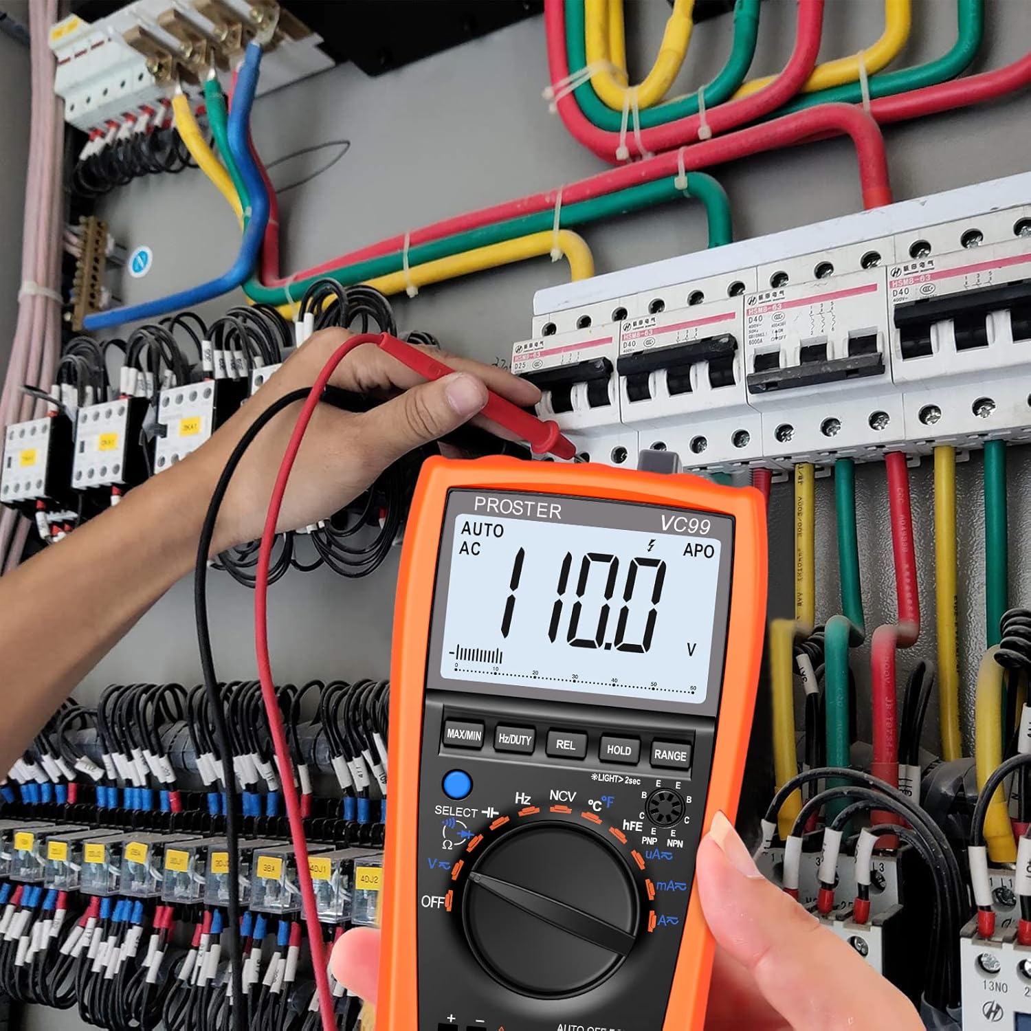
Image: A user measuring AC voltage within an electrical panel using the Proster VC99 Digital Multimeter, showing practical application in a complex circuit.
6.4. Resistance Measurement (Ω)
To measure resistance:
- Ensure the circuit is de-energized before measuring resistance.
- Connect the black test lead to the COM jack and the red test lead to the VΩHz jack.
- Rotate the rotary switch to the Ω position.
- Connect the test leads across the resistor or component.
- Read the resistance value on the LCD display.
6.5. Continuity Test (♫)
To test for continuity (a complete circuit):
- Ensure the circuit is de-energized.
- Connect the black test lead to the COM jack and the red test lead to the VΩHz jack.
- Rotate the rotary switch to the Ω position. Press the SELECT button until the continuity symbol (♫) appears on the display.
- Connect the test leads across the circuit or component.
- If the resistance is below approximately 50Ω, the buzzer will sound, indicating continuity. The display will also show the resistance value.

Image: The multimeter showing a continuity test in progress, with the display indicating a low resistance and a "buzzing" animation, demonstrating the audible alert for continuity.
6.6. Temperature Measurement (℃/℉)
To measure temperature:
- Connect the K-type thermocouple probe to the VΩHz and COM jacks, observing the correct polarity (positive to VΩHz, negative to COM).
- Rotate the rotary switch to the TEMP (℃/℉) position.
- Place the tip of the thermocouple probe on or in the object whose temperature you wish to measure.
- Read the temperature value on the LCD display. Press the SELECT button to switch between Celsius (℃) and Fahrenheit (℉).
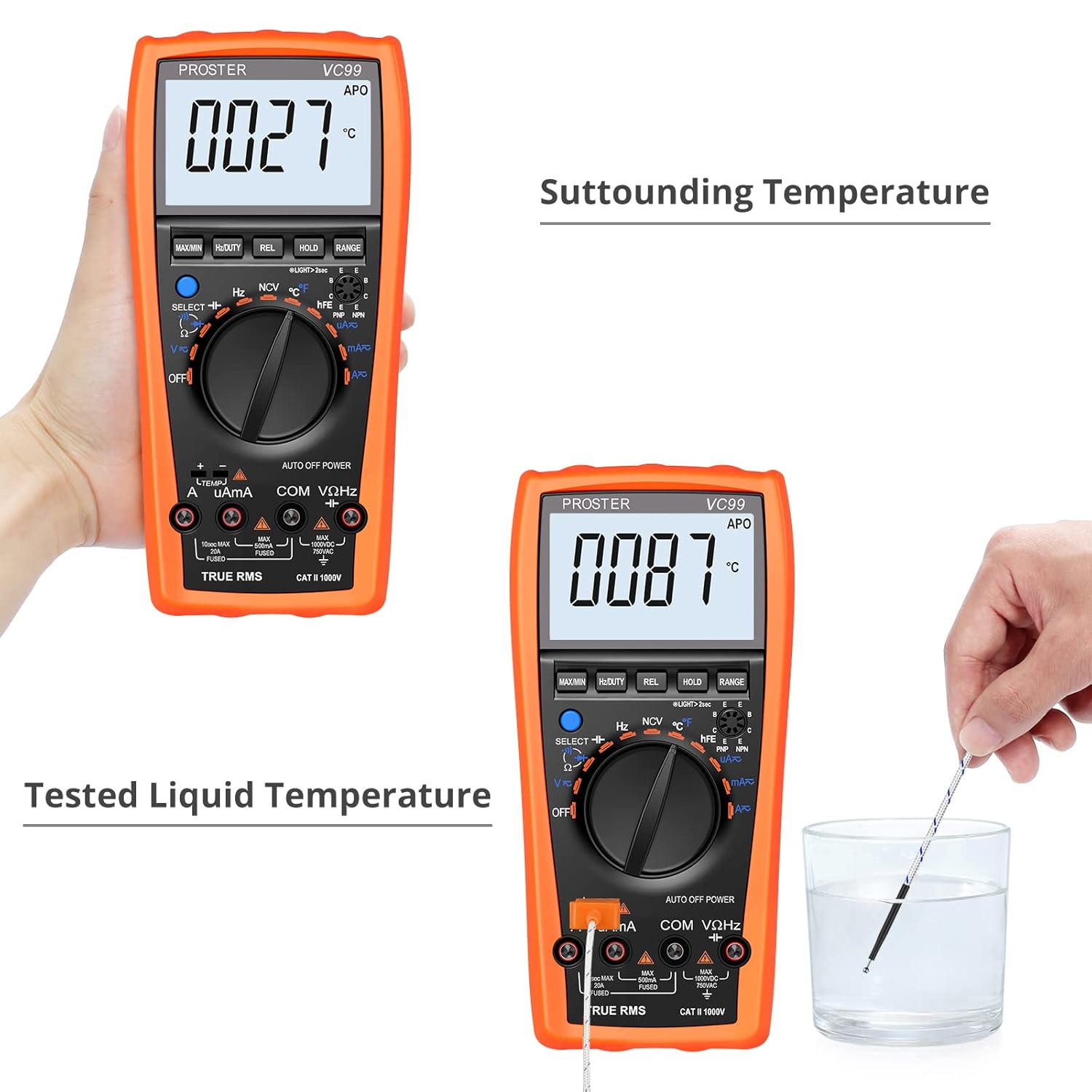
Image: The multimeter demonstrating temperature measurement, showing both ambient temperature (27℃) and liquid temperature (87℃) using the K-type thermocouple probe.
6.7. Non-Contact Voltage (NCV) Detection
The NCV function allows for quick detection of AC voltage without direct contact, useful for identifying live wires.
- Rotate the rotary switch to the NCV position.
- Move the top front part of the multimeter close to the object or wire you suspect has AC voltage.
- If AC voltage is detected, the meter will emit an audible beep and the NCV indicator on the display will illuminate. The frequency of beeps and light intensity increases with stronger signals.

Image: The multimeter in NCV mode, positioned near a power outlet, indicating the non-contact voltage detection function is active and ready to sense live AC voltage.
Note: NCV detection is for preliminary indication only. Always use direct contact voltage measurement for precise and safe verification of live circuits.
6.8. Other Functions
Refer to the detailed instructions in the included user manual for operation of other functions such as DC/AC Current, Capacitance, Frequency, Duty Cycle, Diode Test, and Transistor (hFE) Test.
7. Maintenance
7.1. Cleaning
Wipe the case with a damp cloth and mild detergent. Do not use abrasives or solvents. Keep the input terminals free of dirt and moisture.
7.2. Battery Replacement
When the battery symbol appears on the LCD, the batteries are low and should be replaced immediately to ensure accurate readings. Follow the steps in Section 5.1 for battery installation.
7.3. Fuse Replacement
If the meter fails to measure current, the fuse may be blown. Fuse replacement should only be performed by qualified personnel. Refer to the full user manual for fuse specifications and replacement procedures. Always disconnect test leads and power off the meter before opening the case.
7.4. Storage
If the meter is not to be used for an extended period, remove the batteries to prevent leakage and damage to the meter. Store the meter in a cool, dry place, away from direct sunlight and extreme temperatures.
8. Troubleshooting
| Problem | Possible Cause | Solution |
|---|---|---|
| No display or dim display | Low batteries; Meter OFF | Replace batteries; Turn rotary switch to a function. |
| "OL" (Overload) displayed | Input value exceeds selected range or meter's maximum capacity. | Switch to a higher range (if not in auto-range); Ensure input is within meter's specifications. |
| Incorrect current measurement | Blown fuse; Incorrect input jack used. | Check and replace fuse if necessary; Ensure red lead is in mAʵA or A jack. |
| No continuity beep | Circuit resistance too high; Not in continuity mode. | Ensure resistance is below 50Ω; Press SELECT to activate continuity mode. |
9. Specifications
| Parameter | Specification |
|---|---|
| Display | LCD, 5999 counts, with analog bar graph |
| DC Voltage (V-) | Up to 1000V |
| AC Voltage (V~) | Up to 750V |
| DC Current (A-) | Up to 20A |
| AC Current (A~) | Up to 20A |
| Resistance (Ω) | Up to 60MΩ |
| Capacitance | Up to 2000ʵF |
| Frequency (Hz) | Up to 10MHz |
| Temperature (℃/℉) | -20℃ to 1000℃ (-4℉ to 1832℉) |
| Diode Test | Yes |
| Continuity Test | Yes, with buzzer |
| Transistor (hFE) Test | Yes |
| Non-Contact Voltage (NCV) | Yes |
| Power Supply | 2 x 1.5V AAA Batteries |
| Dimensions | 14.1 x 7.1 x 2.7 cm (5.55 x 2.8 x 1.06 inches) |
| Weight | 590 grams (1.3 lbs) |
| Safety Rating | CAT III 1000V, CAT IV 600V |
10. Warranty and Support
Proster products are designed for reliability and performance. For warranty information or technical support, please refer to the contact details provided with your purchase or visit the official Proster website. Keep your purchase receipt as proof of purchase for warranty claims.
For further assistance, you may contact Proster customer service through their official channels. Please have your model number (FBA_PST99) and purchase details ready when contacting support.
Related documentsFBA_PST99

Ask a question about this manual
Ask about setup, troubleshooting, compatibility, parts, safety, or missing instructions. Manuals+ will review the question and use this page’s manual context to help answer it.