
1. Introduction
This manual provides detailed instructions for the safe and effective use of your Proster PST97 VC97 Digital Multimeter. This device is a versatile, auto-ranging digital multimeter designed for measuring AC/DC voltage, AC/DC current, resistance, capacitance, frequency, diode, transistor (HFE), and continuity. It also includes a temperature measurement function. Please read this manual thoroughly before operation and retain it for future reference.
2. Product Overview
2.1 Key Features
- 4000 Count LCD Display: Provides clear digital readings.
- Auto-Ranging: Automatically selects the appropriate measurement range.
- Comprehensive Measurement Capabilities: Measures AC/DC Voltage, AC/DC Current, Resistance, Capacitance, Frequency, Diode, Transistor (HFE), and Continuity.
- Temperature Measurement: Includes a K-type temperature probe for measuring temperature.
- Data Hold Function: Freezes the displayed reading for easy recording.
- Low Battery Indication: Alerts when battery replacement is needed.
- Overload Protection: Ensures safety across all measurement ranges.
- Protective Rubber Casing: Provides shock and impact resistance.
- Integrated Kickstand: Allows for hands-free operation.
2.2 Components
The Proster PST97 VC97 Digital Multimeter package includes the following items:
- Proster PST97 VC97 Digital Multimeter
- Test Leads (one red, one black)
- K-Type Temperature Probe
- 2 x AAA Batteries (pre-installed or separate)
- Carrying Pouch
- User Manual

Figure 2.2.1: Proster PST97 VC97 Digital Multimeter with included test leads, temperature probe, and carrying pouch.

Figure 2.2.2: Front view of the Proster PST97 VC97 Multimeter showing the display, rotary switch, and input jacks, along with connected test leads and temperature probe.
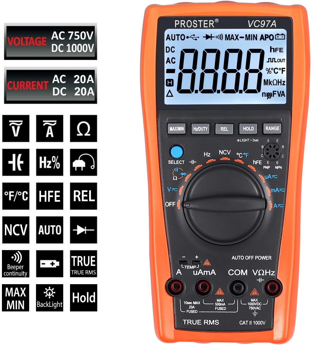
Figure 2.2.3: Display icons indicating various measurement functions supported by the multimeter, including voltage, current, resistance, capacitance, frequency, diode, transistor, continuity, and temperature.
3. Setup
3.1 Battery Installation
- Ensure the multimeter is turned OFF.
- Remove the protective rubber casing.
- Locate the battery compartment cover on the back of the multimeter.
- Unscrew the single screw holding the battery cover.
- Insert two AAA batteries, observing correct polarity (+/-).
- Replace the battery cover and secure it with the screw.
- Re-attach the protective rubber casing.
Note: The multimeter may come with batteries pre-installed. If the display shows a low battery indicator, replace the batteries as described above.
3.2 Connecting Test Leads
Always connect the black test lead to the "COM" (Common) jack. Connect the red test lead to the appropriate input jack based on the measurement type:
- VΩHz: For Voltage, Resistance, Frequency, Capacitance, Diode, and Continuity measurements.
- mAµA: For small current measurements (milliamperes, microamperes).
- A: For large current measurements (amperes, up to 20A).
Ensure test leads are fully inserted into the jacks before taking any measurements.
4. Operating Instructions
Before taking any measurements, ensure the multimeter is set to the correct function and range, and the test leads are connected to the appropriate jacks. Always disconnect power to the circuit before measuring resistance, capacitance, or continuity.
4.1 AC/DC Voltage Measurement (V~ / V-)
- Turn the rotary switch to the "V~" (AC Voltage) or "V-" (DC Voltage) position.
- Connect the black test lead to the "COM" jack and the red test lead to the "VΩHz" jack.
- For AC Voltage, if the multimeter defaults to DC, press the "SELECT" button to switch to AC.
- Connect the test probes in parallel across the circuit or component to be measured.
- Read the voltage value on the LCD.

Figure 4.1.1: Measuring AC voltage from a power outlet using the multimeter. The display shows "AC 110.0V".
4.2 AC/DC Current Measurement (A~ / A-, mAµA~ / mAµA-)
Caution: Never connect the multimeter in parallel for current measurement. Always connect it in series with the circuit. Ensure the circuit is de-energized before connecting the multimeter for current measurement.
- Turn the rotary switch to the "A~" (AC Current), "A-" (DC Current), "mAµA~" (AC mA/µA), or "mAµA-" (DC mA/µA) position.
- Connect the black test lead to the "COM" jack.
- Connect the red test lead to the "mAµA" jack for currents up to 400mA, or to the "A" jack for currents up to 20A.
- Open the circuit where current is to be measured and connect the multimeter in series.
- Apply power to the circuit and read the current value on the LCD.
4.3 Resistance Measurement (Ω)
- Ensure the circuit is de-energized.
- Turn the rotary switch to the "Ω" position.
- Connect the black test lead to the "COM" jack and the red test lead to the "VΩHz" jack.
- Connect the test probes across the component to be measured.
- Read the resistance value on the LCD.
4.4 Capacitance Measurement (F)
- Ensure the capacitor is fully discharged before measurement.
- Turn the rotary switch to the "F" position.
- Connect the black test lead to the "COM" jack and the red test lead to the "VΩHz" jack.
- Connect the test probes across the capacitor.
- Read the capacitance value on the LCD. Measurement may take several seconds for larger capacitors.
- Tip: For more accurate readings, press the "REL" button after connecting the leads but before connecting to the capacitor to zero out any residual capacitance from the leads.

Figure 4.4.1: Measuring the capacitance of an electrolytic capacitor. The display shows "065.2 µF".
4.5 Frequency Measurement (Hz)
- Turn the rotary switch to the "Hz" position.
- Connect the black test lead to the "COM" jack and the red test lead to the "VΩHz" jack.
- Connect the test probes across the signal source.
- Read the frequency value on the LCD.
4.6 Diode Test (symbol: arrow with bar)
- Ensure the circuit is de-energized.
- Turn the rotary switch to the Diode Test position (often indicated by an arrow with a bar symbol).
- Connect the black test lead to the "COM" jack and the red test lead to the "VΩHz" jack.
- Connect the red probe to the anode and the black probe to the cathode of the diode.
- The display will show the forward voltage drop. Reverse the probes; the display should show "OL" (Overload) for a good diode.
4.7 Continuity Test (symbol: sound wave)
- Ensure the circuit is de-energized.
- Turn the rotary switch to the Continuity Test position (often indicated by a sound wave symbol).
- Connect the black test lead to the "COM" jack and the red test lead to the "VΩHz" jack.
- Connect the test probes across the component or circuit path.
- If the resistance is below approximately 50Ω, the buzzer will sound, indicating continuity.
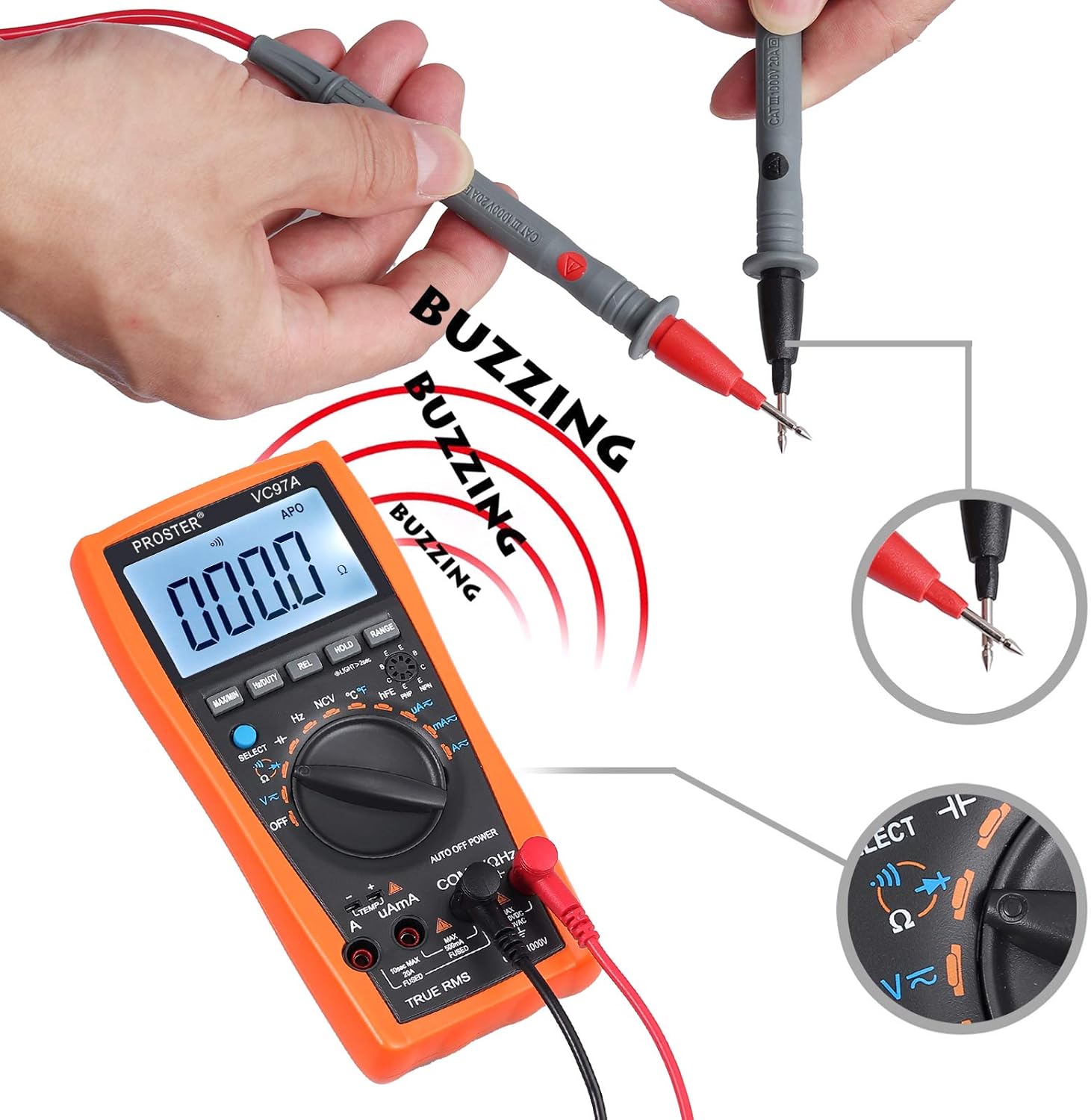
Figure 4.7.1: Performing a continuity test by touching the two test probes together. The display shows "000.0" and a buzzing sound is indicated.
4.8 Transistor HFE Test
- Turn the rotary switch to the "HFE" position.
- Identify if the transistor is NPN or PNP.
- Insert the transistor leads (Emitter, Base, Collector) into the corresponding holes in the HFE socket on the multimeter.
- Read the HFE (DC current gain) value on the LCD.
4.9 Temperature Measurement (°C/°F)
- Turn the rotary switch to the "TEMP" position.
- Connect the K-type temperature probe to the "VΩHz" and "COM" jacks, observing polarity (red to VΩHz, black to COM).
- Place the tip of the temperature probe on or in the object to be measured.
- Read the temperature value on the LCD. Press "SELECT" to switch between Celsius (°C) and Fahrenheit (°F).

Figure 4.9.1: The multimeter displaying surrounding temperature (top) and tested liquid temperature (bottom) using the K-type probe.
4.10 Non-Contact Voltage (NCV) Detection
- Turn the rotary switch to the "NCV" position.
- Move the top part of the multimeter close to the AC voltage source (e.g., a live wire or outlet).
- The multimeter will emit an audible beep and the NCV indicator will light up if AC voltage is detected.

Figure 4.10.1: Using the NCV function to detect AC voltage near a power outlet. The display shows dashes and sound waves indicate detection.
4.11 Special Functions
- HOLD: Press this button to freeze the current reading on the display. Press again to release.
- RANGE: In auto-ranging modes, press this button to switch to manual ranging. Subsequent presses will cycle through available ranges. Press and hold to return to auto-ranging.
- REL (Relative Measurement): Press this button to store the current reading as a reference value. Subsequent measurements will be displayed as the difference from this reference. Useful for zeroing out lead resistance or capacitance.
- Hz/DUTY: In AC Voltage or AC Current modes, press this button to display the frequency or duty cycle of the AC signal.
- MAX/MIN: Press this button to display the maximum or minimum measured value since the function was activated.
- Backlight: Press the "LIGHT" button (often combined with another function, e.g., long press HOLD) to turn on/off the display backlight.
5. Maintenance
5.1 Cleaning
Wipe the multimeter with a damp cloth and mild detergent. Do not use abrasives or solvents. Ensure the device is dry before storage or use.
5.2 Battery Replacement
Refer to Section 3.1 for detailed instructions on replacing the AAA batteries when the low battery indicator appears on the display.
5.3 Fuse Replacement
The multimeter is equipped with internal fuses for protection. If the current measurement functions cease to work, a fuse may need replacement. Replacing the fuses requires disassembling the multimeter casing. This process involves removing the rubber casing, unscrewing the back panel (three screws), and then further disassembling the internal circuit board (additional screws) to access the fuses. Due to the complexity and potential to void warranty, it is recommended that fuse replacement be performed by qualified personnel or the manufacturer's service center.
- 10A Fuse: For the 20A input jack.
- 500mA Fuse: For the mAµA input jack.
Always replace fuses with ones of the identical type and rating.
6. Troubleshooting
| Problem | Possible Cause | Solution |
|---|---|---|
| No display or dim display | Dead or low batteries; incorrect battery installation. | Replace batteries (Section 3.1); ensure correct polarity. |
| "OL" (Overload) displayed | Measurement exceeds selected range or meter's maximum capacity. | Switch to a higher range (if in manual range) or ensure the measured value is within the meter's limits. |
| Incorrect readings | Incorrect function selected; loose test leads; damaged test leads; external interference. | Verify function setting; ensure leads are fully inserted; inspect leads for damage; move away from strong electromagnetic fields. |
| Current measurement not working | Blown fuse. | Replace the appropriate fuse (Section 5.3). |
| Slow capacitance measurement | Normal for large capacitors; residual charge on capacitor. | Allow sufficient time for measurement; ensure capacitor is fully discharged before testing. Use REL function to zero out lead capacitance. |
| Multimeter beeps continuously | Low battery warning; continuity test active. | Check battery indicator and replace if necessary. If in continuity mode, this is normal when continuity is detected. |
7. Specifications
| Feature | Detail |
|---|---|
| Brand | Proster |
| Model Number | VC97 |
| Display | 4000 Counts LCD |
| Power Source | 2 x AAA Alkaline Batteries |
| AC Voltage Range | Up to 750V |
| DC Voltage Range | Up to 1000V |
| AC Current Range | Up to 20A |
| DC Current Range | Up to 20A |
| Resistance Range | Yes |
| Capacitance Range | Up to 200µF |
| Frequency Measurement | Yes |
| Temperature Measurement | Yes (with K-type probe) |
| Diode Test | Yes |
| Continuity Test | Yes (with buzzer) |
| Transistor HFE Test | Yes |
| Non-Contact Voltage (NCV) | Yes |
| Auto Power Off | Yes |
| Dimensions (L x W x H) | 18.5 x 9.3 x 3.5 cm (approx. 7.3 x 3.7 x 1.4 inches) |
| Weight | 290 Grams (approx. 0.64 lbs) |
| Safety Rating | CAT II 1000V |
8. Warranty and Support
Proster products are designed for reliability and performance. For warranty information, technical support, or service inquiries, please refer to the contact details provided with your purchase documentation or visit the official Proster website. Please retain your proof of purchase for warranty claims.
