1. Introduction
Thank you for choosing the ClimaTek Upgraded Replacement Furnace Control Circuit Board. This component is designed to replace original equipment in Payne furnaces, serving as the central control unit for your heating system. Proper installation and understanding of its functions are crucial for safe and efficient operation. Please read this manual thoroughly before proceeding with installation or troubleshooting.
2. Safety Information
WARNING: Installation and servicing of heating equipment can be hazardous due to electrical components and gas connections. This product should only be installed and serviced by a qualified service technician. Failure to follow these instructions could result in property damage, personal injury, or death.
- Always disconnect all electrical power to the furnace before installing or servicing this control board.
- Ensure proper grounding of the furnace and all electrical components.
- Verify all wiring connections are secure and correct according to the furnace manufacturer's specifications and local electrical codes.
- Do not bypass any safety devices.
- Wear appropriate personal protective equipment (PPE) during installation and servicing.
3. Product Overview
The ClimaTek Upgraded Replacement Furnace Control Circuit Board (Model: CECOMINOD056065) is an aftermarket component designed to replace the original control board in compatible Payne furnace models. It manages various furnace operations, including ignition, blower motor control, and safety shutdowns. The board features clearly labeled terminals for easy connection and an integrated fuse for circuit protection.
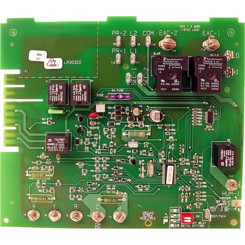
Figure 3.1: ClimaTek Upgraded Replacement Furnace Control Circuit Board. This image displays the green circuit board with various electronic components, relays, and terminal connections. Key labels visible include "PR-2 L2", "PR-1 L1", "COM", "EAC-2", "EAC-1", "BLWR", "HI/LO", "HI", "LO", "3A-FUSE", "W", "Y", "R", "C", "G" terminals, and a "GROUND REQUIRED" indicator. There are also small switches labeled "SW1" for "SWITCH SETTINGS" and an LED indicator. Relays from "TIANBO" and "Tyco Electronics" are present, along with various resistors, capacitors, and integrated circuits. The board also indicates "MAX 1.0 AMPS 115VAC LOAD" for EAC connections and "24VDC FORM A" and "N.O. 30A, 240VAC" for relay specifications.
4. Setup and Installation
Before beginning installation, ensure all power to the furnace is disconnected at the main breaker. Refer to your furnace's specific wiring diagram for detailed instructions. This board is a direct replacement for CES0110057-00.
- Power Disconnection: Turn off the power to the furnace at the main electrical panel. Verify power is off using a voltage meter.
- Access Old Board: Open the furnace access panel and locate the existing control board.
- Disconnect Wiring: Carefully label and disconnect all wires connected to the old control board. Take photos for reference if needed.
- Remove Old Board: Unmount the old control board from its housing.
- Install New Board: Mount the new ClimaTek control board in the same location. Ensure it is securely fastened.
- Connect Wiring: Reconnect all wires to the corresponding terminals on the new board. Refer to Figure 3.1 for terminal identification (e.g., W, Y, R, C, G for thermostat connections; L1, L2 for power input; BLWR for blower motor; EAC-1, EAC-2 for electronic air cleaner). Ensure the "GROUND REQUIRED" screw is properly connected.
- Fuse Installation: Verify the 3A fuse is correctly seated in its holder.
- DIP Switch Settings: Adjust any DIP switches (labeled "SW1" for "SWITCH SETTINGS" on the board) according to your furnace's specific requirements for blower delays or other functions. Consult your furnace manual for correct settings.
- Restore Power: Close the furnace access panel and restore power at the main breaker.
- Test Operation: Initiate a heating cycle to confirm proper operation of the furnace.
5. Operating Instructions
Once installed, the control board operates automatically, managing the furnace's sequence of operations based on thermostat calls and internal safety protocols. The board features an LED indicator that can display diagnostic codes to assist in troubleshooting. Refer to your furnace's manual for a list of diagnostic codes and their meanings.
- Normal Operation: When the thermostat calls for heat, the board initiates the inducer motor, proves draft, ignites the burner, and then activates the blower motor after a set delay.
- Blower Control: The board controls the blower motor's operation, including delays for heating and cooling cycles. These delays may be adjustable via DIP switches.
- Safety Features: The board continuously monitors various safety sensors (e.g., flame sensor, limit switches) and will shut down the furnace if a fault is detected, often indicating the issue via the diagnostic LED.
6. Maintenance
The ClimaTek control board itself requires minimal maintenance. However, regular maintenance of the overall furnace system is recommended to ensure its longevity and proper function.
- Annual Inspection: Have a qualified technician inspect your furnace annually. They can check the control board for any signs of wear, loose connections, or corrosion.
- Cleanliness: Ensure the area around the control board is free from dust, debris, and moisture, which can interfere with electronic components.
- Fuse Check: If the furnace fails to operate, check the 3A fuse on the control board. Replace it only with a fuse of the same type and rating.
7. Troubleshooting
Before attempting any troubleshooting, ensure all power to the furnace is disconnected. If you are not comfortable performing these steps, contact a qualified HVAC technician.
| Problem | Possible Cause | Solution |
|---|---|---|
| Furnace not starting or no power. | No power to furnace, blown fuse on board, loose wiring connection. | Check furnace breaker. Inspect 3A fuse on the control board (Figure 3.1) and replace if blown. Verify all power connections to the board are secure. |
| Blower motor runs continuously. | Incorrect DIP switch settings, stuck relay, thermostat wiring issue. | Verify DIP switch settings (SW1) match furnace specifications for blower delays. Check thermostat wiring for shorts. If problem persists, professional diagnosis may be required. |
| Furnace cycles on and off rapidly (short cycling). | Dirty air filter, restricted airflow, faulty limit switch, incorrect board settings. | Replace dirty air filter. Check for blocked return or supply vents. Consult furnace manual for diagnostic codes displayed by the board's LED. |
| No heat, but blower runs. | Ignition failure, flame sensor issue, gas supply problem. | Check for gas supply. Observe the LED for diagnostic codes related to ignition or flame sensing. Clean flame sensor if accessible. |
For advanced troubleshooting or if the issue persists, consult a qualified HVAC technician. The board's LED indicator provides valuable diagnostic information; refer to your furnace's specific manual for code interpretations.
8. Specifications
| Feature | Detail |
|---|---|
| Product Model Number | CECOMINOD056065 |
| Replacement For | Payne Furnace Control Circuit Board CES0110057-00 |
| Brand | ClimaTek |
| Manufacturer | Universal |
| Product Dimensions | 8 x 6 x 10 inches (packaging); 15 ounces |
| EAC Load Rating | Max 1.0 Amps, 115VAC Load |
| Relay Specifications (General) | 24VDC Form A, N.O. 30A 240VAC; N.C. 10A 240VAC |
| Fuse | 3A (on-board) |
9. Warranty and Support
For specific warranty information regarding your ClimaTek Upgraded Replacement Furnace Control Circuit Board, please refer to the documentation provided with your purchase or contact the seller directly. Warranty terms can vary based on the retailer and purchase date.
If you require technical support or have questions not covered in this manual, please contact the seller or a qualified HVAC professional. Provide your product model number (CECOMINOD056065) and details of your issue for efficient assistance.


