
LiftMaster 41AC050-2M
LiftMaster Garage Door Opener 41AC050-2M Receiver Logic Board
User Manual
Introduction
This manual provides detailed instructions for the installation, operation, and maintenance of the LiftMaster 41AC050-2M Receiver Logic Board. This component is a direct replacement for the logic board found in compatible LiftMaster garage door openers. Proper installation and understanding of its functions are crucial for the safe and efficient operation of your garage door system.
Safety Information
Always prioritize safety when working with electrical components and garage door systems. Failure to follow these safety guidelines could result in serious injury or property damage.
- Disconnect Power: Before beginning any installation or maintenance, always unplug the garage door opener from its power source to prevent electrical shock.
- Professional Assistance: If you are unsure about any step of the installation process, consult a qualified garage door technician.
- Original Manual: Refer to your original garage door opener's user manual for comprehensive safety warnings and operational procedures.
- Door Force Adjustment: To reduce the risk of severe injury or death by entrapment, when adjusting either the force or limits of travel, controls ensure that the door reverses on a 1-inch object (or a 2 x 4 board laid flat). See instructions for proper adjustment procedure in your opener's main manual.
Compatibility
This logic board is a replacement for LiftMaster garage door openers that specifically use the 41AC050-2M logic board. To ensure compatibility, locate the part number on the control panel of your existing garage door opener. The part number typically begins with "41Axxxx-xx".
Installation/Setup
The following steps outline the general procedure for replacing the logic board. Specific details may vary slightly depending on your garage door opener model.
- Disconnect Power: Unplug the garage door opener from the electrical outlet.
- Access Board: Remove the back cover of the garage door opener and the light bulb to gain access to the existing logic board assembly.
- Document Connections: Before disconnecting any wires or connectors, it is highly recommended to take clear photographs of all wiring and connector placements. This will serve as a valuable reference during reassembly.
- Remove Old Board: Carefully disconnect all wires from the terminal block and the two internal connectors. Remove the screws (typically three: two on top, one on the bottom) securing the back panel with the old logic board. Gently remove the entire assembly.
- Install New Board: Align the new 41AC050-2M logic board assembly with the mounting points. Reconnect the two internal connectors, ensuring they are properly oriented and seated. Reattach the screws to secure the new assembly.
- Reconnect Wires: Refer to your photographs to reconnect all wires to the terminal block exactly as they were on the old board. Ensure all connections are secure.
- Reassemble: Replace the light bulb and the back cover of the garage door opener.
- Restore Power: Plug the garage door opener back into the electrical outlet.
- Reprogram Remotes: After installation, you will need to reprogram your garage door remotes and external keypads. Refer to the 'Operating' section for programming instructions.
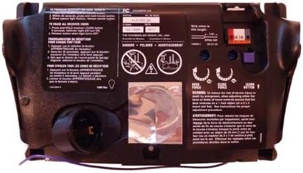
Image: Rear view of a LiftMaster garage door opener with the 41AC050-2M receiver logic board installed. Visible components include the wiring terminal block, the light bulb socket, and the purple 'LEARN' button for programming remotes. The image also displays important safety warnings and programming instructions printed on the unit's casing.
Operating
Once the new logic board is installed, you will need to program your remote controls and keypads to the opener.
To Program a Remote Control:
- Press and release the 'LEARN' button (often purple) on the garage door opener's control panel. The LED indicator light will turn on.
- Within 30 seconds, press and hold the button on your remote control that you wish to operate the garage door.
- Release the remote button when the opener's light flashes or two clicks are heard. This indicates successful programming.
To Erase All Receiver Codes:
If you need to clear all previously programmed remote controls and keypads from the opener's memory:
- Press and hold the 'LEARN' button on the garage door opener until the LED indicator light turns off (approximately 6 seconds).
- All previous codes are now erased. You will need to reprogram all desired remote controls and keypads.
Maintenance
The 41AC050-2M Receiver Logic Board is designed for durability and typically requires minimal maintenance. However, regular inspection of your garage door opener system is recommended.
- Visual Inspection: Periodically inspect the logic board area for any signs of dust, debris, or loose connections.
- Cleanliness: Keep the area around the logic board clean and free from obstructions. Use a soft, dry cloth to gently wipe away any dust. Do not use liquids or harsh chemicals.
- Connection Check: Ensure all wires connected to the logic board's terminal block are secure and not frayed.
Troubleshooting
If you encounter issues after installing the new logic board, consider the following common problems and solutions:
- Opener Not Responding: Ensure the opener is plugged in and receiving power. Double-check all wire connections to the logic board and terminal block.
- Remotes Not Working: If remotes do not operate the door, they likely need to be reprogrammed to the new logic board. Follow the instructions in the 'Operating' section.
- Door Moves Briefly Then Stops (e.g., 6-8 inches): This can indicate that the opener's travel limits or force settings are out of phase. This is not typically a logic board defect but requires recalibration of the opener's travel. Refer to your garage door opener's main manual for instructions on adjusting travel limits and force. This often involves disconnecting the chain from the gear, running the opener to reset its internal position, and then reattaching the chain and recalibrating.
- No Lights/No Power: If the opener has no power or lights, verify the power supply. If power is present but the unit is completely unresponsive, the logic board may be faulty or incorrectly installed. Re-check all connections.
If problems persist after troubleshooting, it is recommended to contact LiftMaster customer support or a certified garage door technician.
Specifications
| Part Number | 41AC050-2M |
| Item Weight | 1.52 pounds |
| Package Dimensions | 12.36 x 6.81 x 4.09 inches |
| Manufacturer | The Chamberlain Group |
| Item Package Quantity | 1 |
| Batteries Required? | No |
Warranty and Support
For specific warranty information regarding your LiftMaster 41AC050-2M Receiver Logic Board, please refer to the documentation included with your purchase or visit the official LiftMaster website. For technical support, troubleshooting assistance, or to inquire about replacement parts, contact LiftMaster customer service directly. Ensure you have your product model number and any relevant purchase information ready when contacting support.
LiftMaster Official Website: www.liftmaster.com
Ask a question about this manual
Ask about setup, troubleshooting, compatibility, parts, safety, or missing instructions. Manuals+ will review the question and use this page’s manual context to help answer it.