1. Important Safeguards
When using electrical equipment, basic safety precautions should always be followed, including the following:
- Do not let power supply cords touch hot surfaces.
- Do not mount near gas or electric heaters.
- Equipment should be mounted in locations and at heights where it will not readily be subject to tampering by unauthorized personnel.
- The use of accessory equipment not authorized by the manufacturer may cause an unsafe condition.
- Do not use this equipment for other than its intended purpose.
- Servicing of this equipment should be performed by qualified service personnel.
WARNING: This product contains chemicals known to the State of California to cause cancer, birth defects and/or other reproductive harm. Thoroughly wash hands after installing, handling, cleaning, or otherwise touching this product.
WARNING: Make sure that power is OFF before making any Electrical Connections.
Unused wires must be capped using enclosed wire nuts.

Image: Important Safeguards and Installer Information. This image displays critical safety warnings and installation guidelines for the emergency light, emphasizing the need for qualified personnel for servicing.
2. Product Overview
The Hubbell Compass CU2RC is a dual-head LED emergency light designed for commercial applications. It features a durable thermoplastic housing and adjustable lamp heads for versatile lighting direction.
Key Features:
- Reliable Lighting: Suitable for emergency or security backup in commercial areas such as pool areas, parking decks, hallways, offices. NFPA 101, NFPA 70, and OSHA certified.
- Energy-Efficient: LED system with a 10-year lifespan.
- Extended Use Battery: Nickel-cadmium battery provides 90 minutes of emergency power during outages.
- Durable Material: White high-impact flame-rated thermoplastic housing.
- Mounting Versatility: Can be mounted on walls or ceilings.
- Dual-Voltage Input: Supports 120/277 AC input.
- Remote Capacity: Ability to power up to two external indoor or outdoor remote lamps.
- Test Switch: Water-proof self-test switch for battery/charger monitoring.

Image: Hubbell Compass CU2RC Emergency Light Features. This image highlights the white thermoplastic housing, remote capacity, fully adjustable lamp-heads, and the test button/AC-ON indicator.

Image: Emergency Light Usage Locations. This image indicates that the product is suitable for use in conditioned spaces, damp locations, stairwells, hallways, offices, retail, or commercial settings.
3. Specifications
| Feature | Detail |
|---|---|
| Model Number | CU2RC |
| Manufacturer | Compass (Hubbell) |
| Item Weight | 1 pound |
| Product Dimensions | 3 x 9 x 4 inches (Depth x Width x Height) |
| Color | White |
| Material | Plastic (Thermoplastic) |
| Power Source | AC/DC |
| Voltage | 120/277 Volts (AC) |
| Wattage | 1 watt |
| Type of Bulb | LED |
| Mounting Type | Ceiling Mount, Wall Mount |
| Battery Type | Nickel Oxyhydroxide (Product Specific, included) |
| Emergency Run Time | 90 minutes |
| Certifications | NFPA 101, NFPA 70, OSHA, UL924, Title 20 |

Image: Product Dimensions Diagram. This diagram illustrates the unit's dimensions: 9 inches in width, 4 inches in height, and 2.75 inches in depth.

Image: Key Specifications of Emergency Light. This graphic highlights the LED life-cycle of more than 10 years, dual-voltage 120/277 AC input, and the Nickel Cadmium battery for UL recognized 90-minute emergency lighting.

Image: Emergency Light Material and Finish. This image shows the product and specifies its material as thermoplastic and its finish as white.
4. Installation
The unit is designed for quick and easy installation. Ensure power is OFF before beginning any electrical connections.
4.1 J-Box Mounting
- Feed fixture leads through main bottom case and connect AC power supply.
- Connect wires through J-Box. Secure back plate on to J-Box with screws.
- Connect battery only after AC power can be provided to the unit.
- Align snaps and push housing directly onto back plate. Supply AC power and press "TEST" button to check light.
4.2 Conduit Mounting
- Secure back plate to wall surface. Route wires through hole in conduit flange and make conduit connection.
- Connect battery only after AC power can be provided to the unit.
- Align snaps and push housing directly onto back plate. Supply AC power and press "TEST" button to check light.
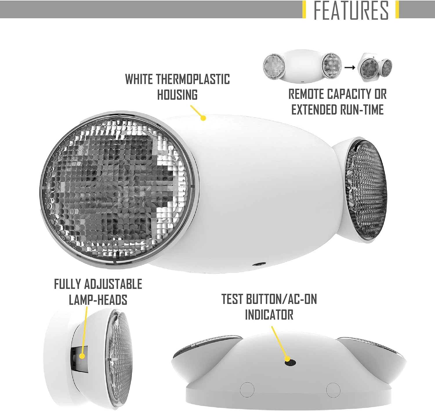
Image: Installation Figure A: J-Box Mounting. This diagram shows the initial wiring connections for J-Box mounting.

Image: Installation Figure B: Battery Connection. This diagram illustrates how to connect the battery within the unit.

Image: Installation Figure C: Housing Assembly. This diagram shows the final step of aligning and pushing the housing onto the back plate.
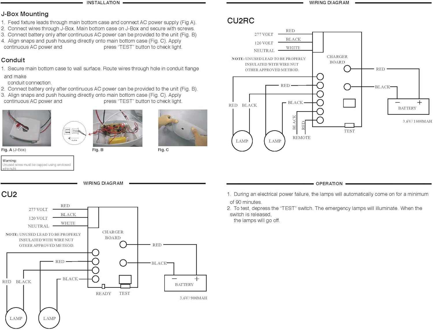
Image: Wiring Diagram for CU2RC. This diagram illustrates the electrical connections for the CU2RC model, including the charger board, battery, and lamp connections for both 120V and 277V inputs.
5. Operation
Once the unit is properly installed according to the installation instruction sheet and AC power supplied, it will come ON. The dual color LED indicator will also come ON and the self-diagnostic test function will automatically initiate.
5.1 Initial Operation
- During an electrical power failure, the lamps on the unit will automatically come ON for a minimum of 90 minutes.
- To test this unit, let it charge correctly with AC power supply for a minimum of 24 hours after its first installation and then depress the "TEST" switch; the emergency lamps will illuminate. When the switch is released, the lamps will turn OFF.
- For the unit with Self-Diagnostic, connect as below:
- When customer doesn't need remote lamp, please insert terminal to N.
- When customer needs remote lamp, please insert terminal to Y.
5.2 Self-Diagnostic Service
The self-diagnostic function is factory preset without any allowable field adjustment. The automatic self-diagnostic feature serves the following tests:
- On-line real time monitoring of battery and lamps (both local and remote) indicates battery charging, disconnection and failure along with local and remote lamp failures.
- Self-testing and a 15-minute discharge once every 30 days, after AC power has been supplied for a minimum of 24 hours.
- Self-testing and a 90-minute discharge once every year, after AC power has been supplied for a minimum of 24 hours.
5.3 Manual Testing
The unit also provides for manual testing by pushing the test button in a specific pattern. The different patterns and the resulting tests are listed in the table below:
| Action | Reaction & LED Indication |
|---|---|
| Push test button Once (within 2 seconds) | 30-second test: FLASHING Green |
| Push test button Twice (within 2 seconds) | 15-minute test: Green BLINKING twice |
| Push test button Three times (within 2 seconds) | 90-minute test: Green Blinking three times |

Image: Self-Diagnostic and Manual Testing Instructions. This image details the self-diagnostic service features, fault indications with corresponding LED signals, and a table for manual testing procedures and their outcomes.
6. Maintenance
The emergency light unit requires minimal maintenance. Regular testing ensures the battery and lamps are functioning correctly.
6.1 Battery Maintenance
The unit is equipped with a long-life nickel-cadmium battery. The self-diagnostic feature automatically performs monthly 15-minute tests and annual 90-minute tests to ensure battery health. If a battery failure is indicated (Red BLINKING '2' TIMES), the battery may need replacement.
6.2 Cleaning
Clean the exterior of the unit with a soft, damp cloth. Do not use abrasive cleaners or solvents.
7. Troubleshooting
The self-diagnostic system provides fault indications via the LED. Refer to the table below for common fault descriptions and their corresponding LED indications.
| Fault Description | LED Indication |
|---|---|
| Battery Disconnection | STEADY Red |
| Battery Recharge Failure | FLASHING Red |
| Battery Failure | Red BLINKING '2' TIMES |
| LED Failure (Exits Only) | Red BLINKING '3' TIMES |
| Remote Lamp Failure (Emergency Lights Only) | Red BLINKING '4' TIMES |
If a fault persists after attempting basic troubleshooting, contact qualified service personnel.
8. Warranty Information
Hubbell Lighting, Inc. ("Hubbell") warrants to the original end user that its products will be free from defects in material and workmanship for the periods specified below.
- Full Unit Warranty: 2 years from the date of shipment.
- LED Fixtures and LED Drivers: 5 years from the date of shipment.
- Batteries: 90 days from the date of shipment.
This warranty is subject to certain exclusions and limitations. For complete warranty details, refer to the full unit warranty document provided with the product or available from Hubbell Lighting, Inc.
Limitation of Liability: In no event shall Hubbell be liable for any indirect, special, incidental, consequential, exemplary, punitive or multiple damages, even if informed of the possibility of such damages.

Image: Product Certifications and Hubbell Warranty. This image displays various certifications such as UL924, Title 20, NFPA 70, NFPA 101, and the Hubbell Warranty shield, indicating compliance and product assurance.
9. Customer Support
For technical assistance, warranty claims, or additional information, please contact Hubbell Lighting customer service.
Visit the official Hubbell Lighting website for more resources: www.hubbell.com/hubbelllighting/en


