
1. Product Overview
The Watts 3/4 inch Lead Free Reduced Pressure Zone (RPZ) Assembly is engineered to safeguard potable water supplies from contamination due to backsiphonage or backpressure. This device complies with national plumbing codes and water authority requirements, making it suitable for continuous pressure piping applications and cross-connections identified as health hazards.

Image 1.1: The Watts 3/4 inch Reduced Pressure Zone Backflow Preventer assembly.

Image 1.2: Visual representation emphasizing the backflow preventer's role in protecting potable water supplies.
Key Features:
- Durable Construction: Features a lead-free bronze body for longevity and compliance.
- NPT Connections: Equipped with National Pipe Tapered (NPT) inlet and outlet connections for secure installation.
- Integrated Shutoffs: Includes quarter-turn, full-port, resilient-seated ball valve shutoffs for easy control.
- Simplified Maintenance: Designed with a single access cover and modular check construction to facilitate in-line repairs and maintenance.
- Low Pressure Drop: Large body passages ensure minimal pressure loss across the assembly.
- Safety Features: Captured springs enhance safety during maintenance procedures.
- Test Cocks: Top-mounted test cocks are included for convenient testing and verification of proper operation.
2. Safety Information
Always adhere to local plumbing codes and regulations during installation and maintenance. This device must be installed by a qualified professional. Failure to follow instructions may result in property damage or injury.
- Ensure the water supply is shut off and depressurized before beginning any work.
- Wear appropriate personal protective equipment (PPE), including safety glasses and gloves.
- Do not install backflow preventers in pits unless explicitly approved by local codes.

Image 2.1: Important note regarding installation of backflow preventers in pits. Always consult local codes.
3. Installation Instructions
Proper installation is crucial for the effective operation of the backflow preventer. This device should be installed in a location that allows for easy access for testing and maintenance.
3.1 Pre-Installation Checks
- Verify that the assembly size (3/4 inch) matches the pipe size.
- Inspect the unit for any visible damage that may have occurred during shipping.
- Ensure all necessary tools and materials are available, including pipe sealant or thread tape.
3.2 Installation Steps
- Prepare Piping: Ensure the piping is clean and free of debris. The assembly must be installed horizontally, with the relief valve pointing downwards.
- Orient the Valve: Observe the flow arrow cast into the valve body to ensure correct orientation with the direction of water flow.
- Connect to Piping: Apply appropriate pipe sealant or thread tape to the NPT connections. Carefully thread the assembly onto the pipes, ensuring a tight, leak-free seal. Avoid overtightening.
- Support the Assembly: Provide adequate support for the assembly to prevent stress on the piping connections.
- Open Shutoff Valves: Slowly open the inlet and outlet shutoff valves to allow water to fill the assembly. Bleed any trapped air from the system.
- Check for Leaks: After installation and pressurization, thoroughly inspect all connections for leaks.

Image 3.1: Close-up view of the valve body, highlighting the flow direction arrow for proper installation.

Image 3.2: A technician connecting the backflow preventer to the plumbing system.
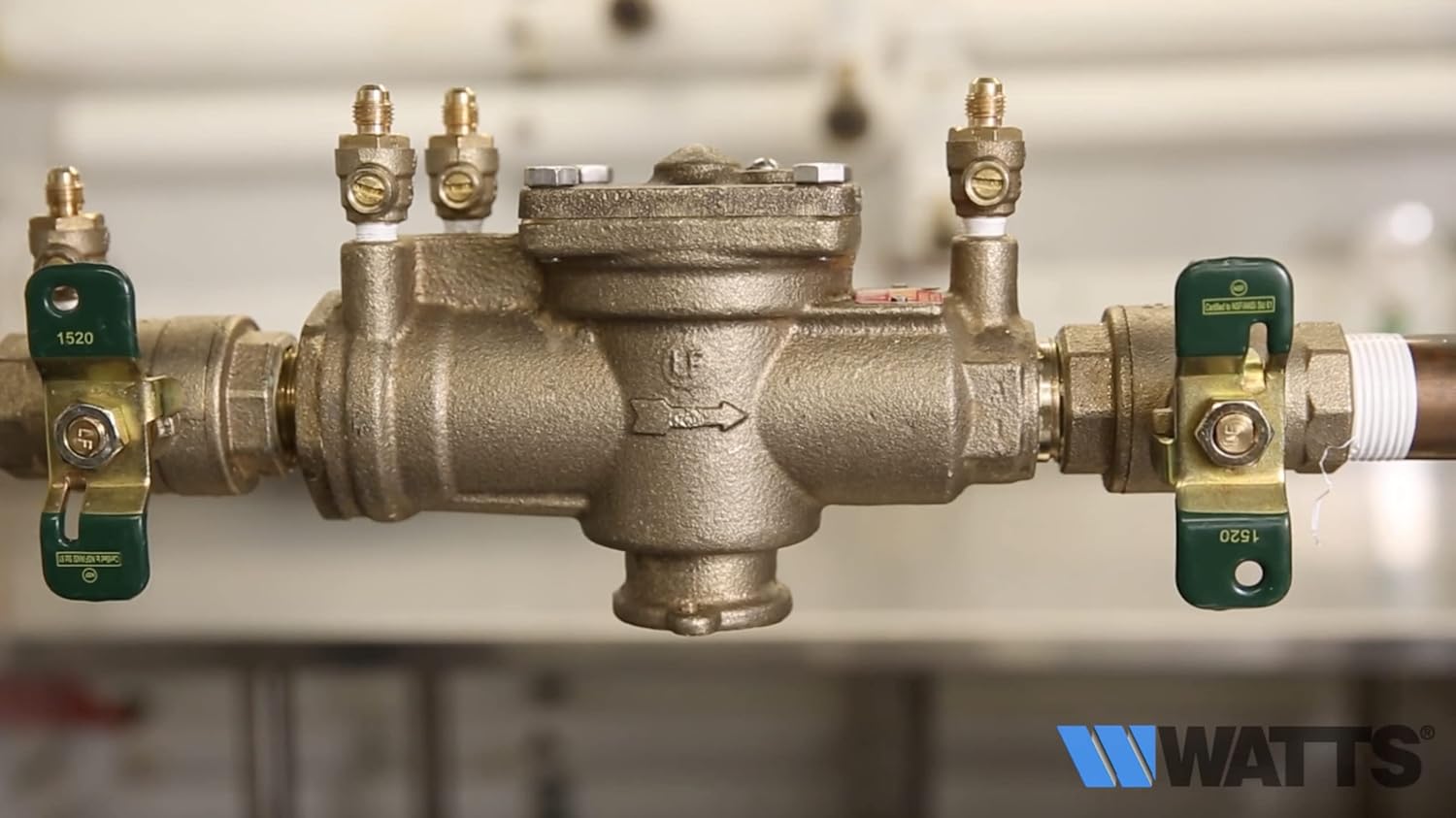
Image 3.3: The Watts backflow preventer fully installed within a plumbing system, ready for operation.
4. Operating Instructions
The Watts Reduced Pressure Zone Assembly operates automatically to prevent backflow. No manual intervention is required during normal operation.
4.1 Normal Operation
- Under normal flow conditions, both check valves are open, and the relief valve remains closed.
- If a backpressure condition occurs, the first check valve closes, maintaining a pressure differential.
- If backsiphonage occurs, both check valves close, and the relief valve opens to discharge water, preventing contaminated water from entering the potable supply.
4.2 Shutoff Valves
The integrated quarter-turn ball valve shutoffs are for isolating the unit for maintenance or testing. Ensure they are fully open during normal operation to allow unrestricted flow.
5. Maintenance
Regular maintenance and testing are essential to ensure the continued proper function of the backflow preventer. Local codes typically require annual testing by a certified backflow prevention device tester.
5.1 Routine Testing
- Annual testing by a certified professional is mandatory in most jurisdictions. The top-mounted test cocks are designed for this purpose.
- Keep records of all tests and maintenance performed.
5.2 Internal Component Access
The single access cover and modular check construction allow for easy inspection and replacement of internal components if necessary.
- Isolate the unit by closing both inlet and outlet shutoff valves.
- Depressurize the assembly by opening the test cocks.
- Remove the bolts securing the access cover.
- Carefully lift the cover to access the check valve assemblies and relief valve.
- Inspect components for wear, damage, or debris. Replace any worn or damaged parts with genuine Watts replacement parts.
- Reassemble in reverse order, ensuring proper seating of all components and tightening bolts evenly.
- Slowly repressurize the system and check for leaks.

Image 5.1: View of the internal components after removing the access cover, showing the check valve assemblies.
6. Troubleshooting
This section addresses common issues that may arise with the backflow preventer. For complex problems, contact a certified professional.
| Problem | Possible Cause | Solution |
|---|---|---|
| Water leaking from relief valve |
|
|
| Reduced water flow |
|
|
| External leaks from body or connections |
|
|
7. Specifications
| Attribute | Value |
|---|---|
| Model Number | LF009M3-QT |
| Size | 3/4 inch |
| Material | Lead-Free Bronze |
| Inlet Connection Size | 0.75 Inches |
| Inlet Connection Type | National Pipe Tapered (NPT) |
| Outlet Connection Size | 3/4 Inches |
| Outlet Connection Type | NPT |
| Maximum Operating Pressure | 175 PSI (Pound per Square Inch) |
| Number of Ports | 3 |
| Dimensions (L x W x H) | Approximately 4 x 4 x 6 inches |
| Item Weight | 5.48 pounds |
| UPC | 098268705553 |
8. Warranty Information
Watts products are manufactured to high standards and are typically covered by a limited warranty. For specific warranty terms and conditions applicable to your Watts LF009M3-QT Reduced Pressure Zone Assembly, please refer to the warranty documentation included with your product or visit the official Watts website. Warranty claims usually require proof of purchase and adherence to installation and maintenance guidelines.
9. Customer Support
For technical assistance, replacement parts, or further information regarding your Watts 3/4" Reduced Pressure Zone Backflow Preventer, please contact Watts customer support.
- Watts Official Website: www.watts.com
- Refer to the product packaging or the Watts website for current contact information (phone numbers, email).


