Introduction
Thank you for choosing the Audiopipe APCL3002 1500 Watt 2 Channel Amplifier. This manual provides essential information for the proper installation, operation, and maintenance of your amplifier. Please read this manual thoroughly before attempting installation or operation to ensure optimal performance and safety.
Safety Information
- Professional Installation Recommended: Installation of car audio equipment can be complex. It is highly recommended that a qualified professional install this amplifier.
- Power Source: Ensure the vehicle's battery is disconnected before starting any wiring to prevent electrical shorts and damage.
- Proper Wiring: Use appropriate gauge wiring for power, ground, and speaker connections as specified in this manual. Incorrect wiring can lead to overheating, fire, or equipment failure.
- Ventilation: Mount the amplifier in a location that allows for adequate air circulation to prevent overheating. Do not cover the amplifier's cooling fins or fan.
- Moisture and Heat: Avoid mounting the amplifier in areas exposed to direct sunlight, excessive heat, or moisture.
- Fuse Protection: Always use the correct fuse rating as specified. Never replace a fuse with one of a higher rating.
Product Overview
The Audiopipe APCL3002 is a powerful 2-channel amplifier designed to enhance your car audio system. It features adjustable gain, bass boost, and crossover controls for precise sound tuning.
Amplifier Components and Controls

Image: Rear Connections. This image displays the rear panel of the Audiopipe APCL3002 amplifier. Visible are the speaker output terminals (Left and Right, with bridging option indicated), the power supply terminals (Ground, Remote, +12V), and two 25A MAX fuses. These connections are crucial for power delivery and audio output.

Image: Front Controls. This image shows the front panel of the Audiopipe APCL3002 amplifier. It features the RCA input jacks (L and R), a GAIN control knob with settings from 0.2V to 6V, a BASS BOOST control (0-15dB) with frequency adjustment, a CROSSOVER section with FREQ range and FILTER type (LP, HP, OFF, STEREO), and a MODE switch for STEREO or BRIDGED MONO operation. These controls allow for fine-tuning of the audio output.

Image: Bottom Cooling Fan. This image provides a view of the bottom of the Audiopipe APCL3002 amplifier, highlighting a circular cooling fan. This fan is essential for dissipating heat and maintaining optimal operating temperatures for the amplifier's internal components.
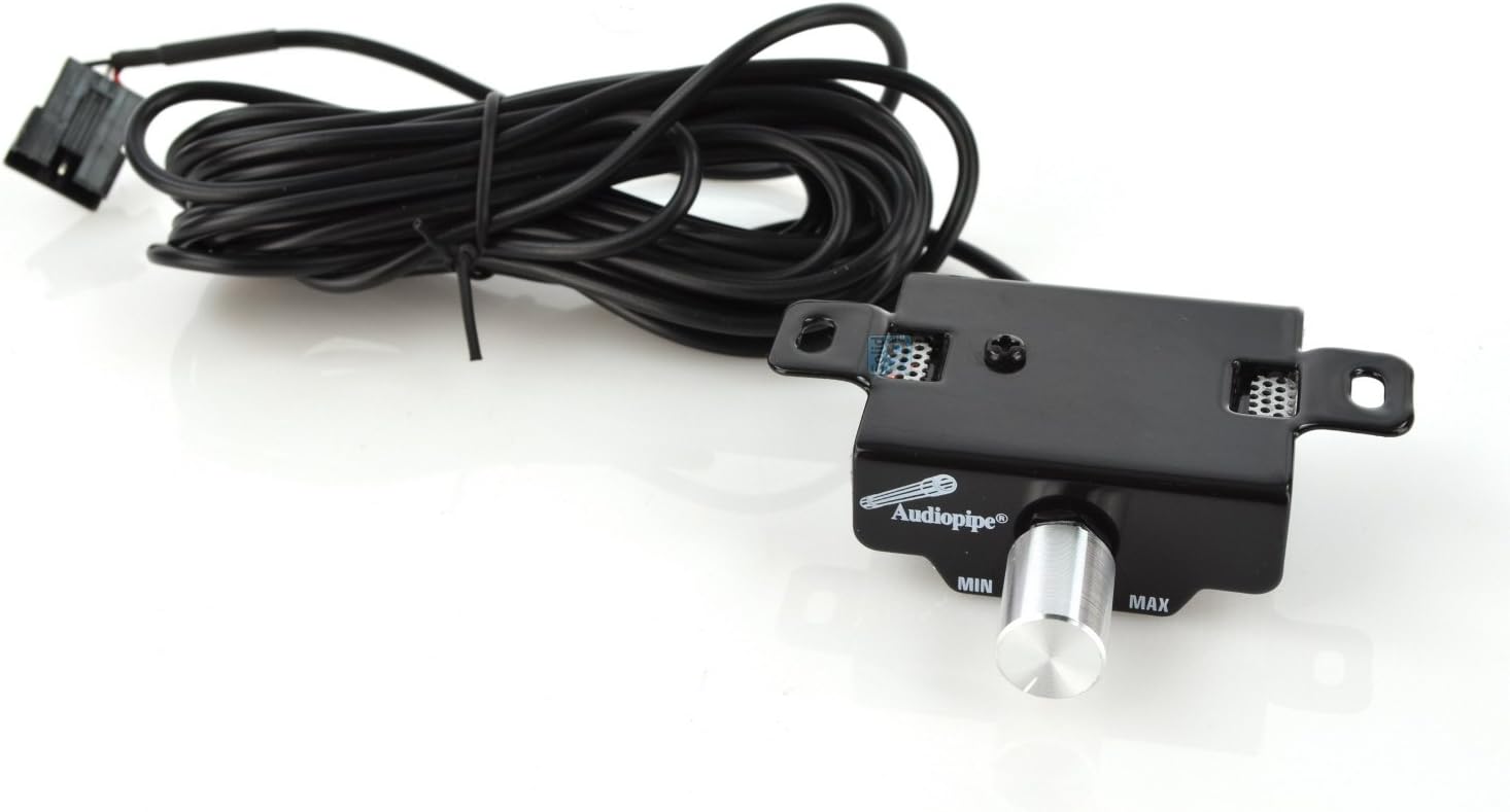
Image: Remote Bass Control. This image shows the external remote bass level control unit for the Audiopipe APCL3002 amplifier. It features a rotary knob labeled 'MIN' to 'MAX' for adjusting the bass output, connected via a cable. This allows for convenient bass level adjustments from the driver's seat.
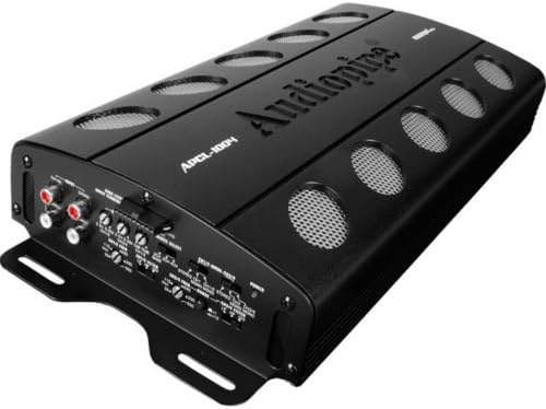
Image: Angled View of Amplifier. This image presents an angled perspective of the Audiopipe APCL3002 amplifier, showcasing its overall design and compact form factor. The top panel with the Audiopipe logo and cooling vents is visible, along with a glimpse of the side panels.
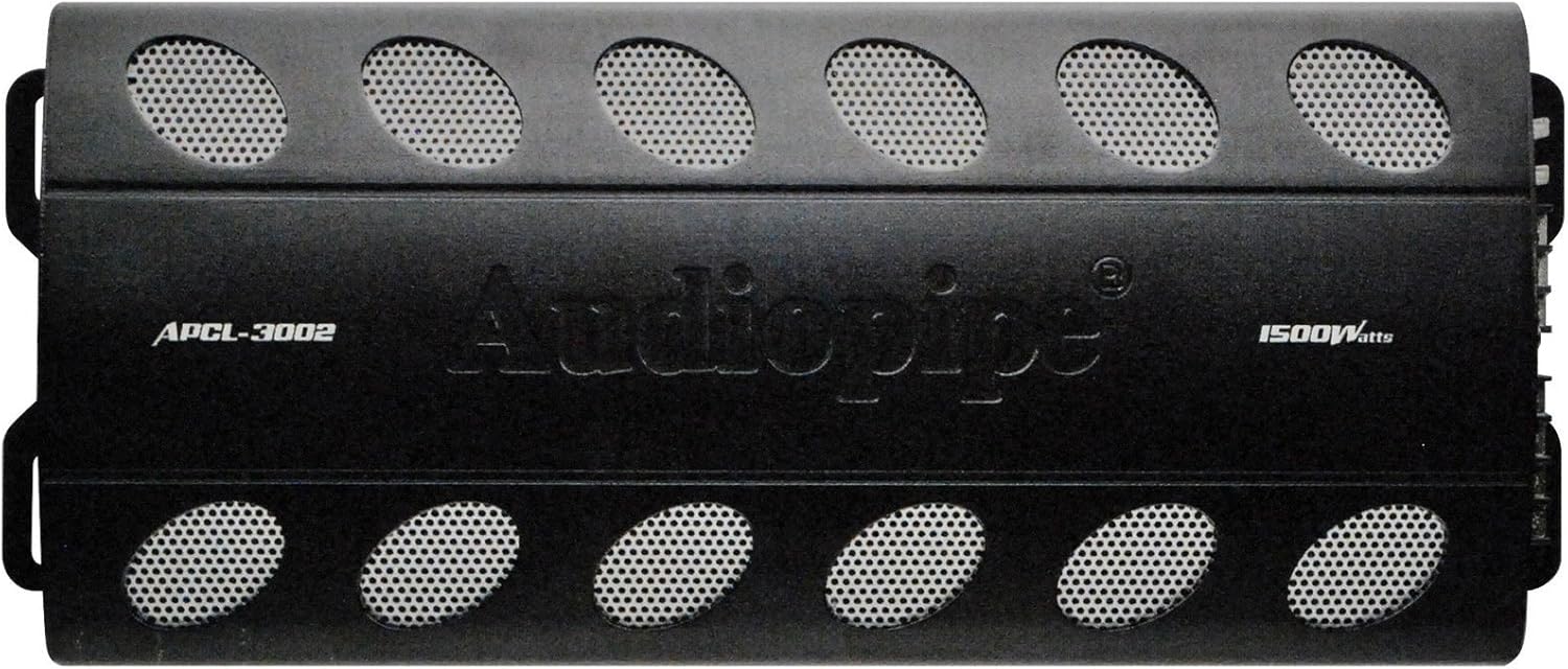
Image: Top View of Amplifier. This image displays the top surface of the Audiopipe APCL3002 amplifier. The Audiopipe brand name is prominently featured, along with the model number APCL-3002 and '1500 Watts' power rating. Multiple oval-shaped cooling vents are visible across the top, designed to aid in heat dissipation.

Image: Wiring Harness. This image shows a multi-colored wiring harness, typically used for connecting the amplifier to various components like the remote turn-on signal or other low-current connections. The wires are bundled and secured with a twist tie.
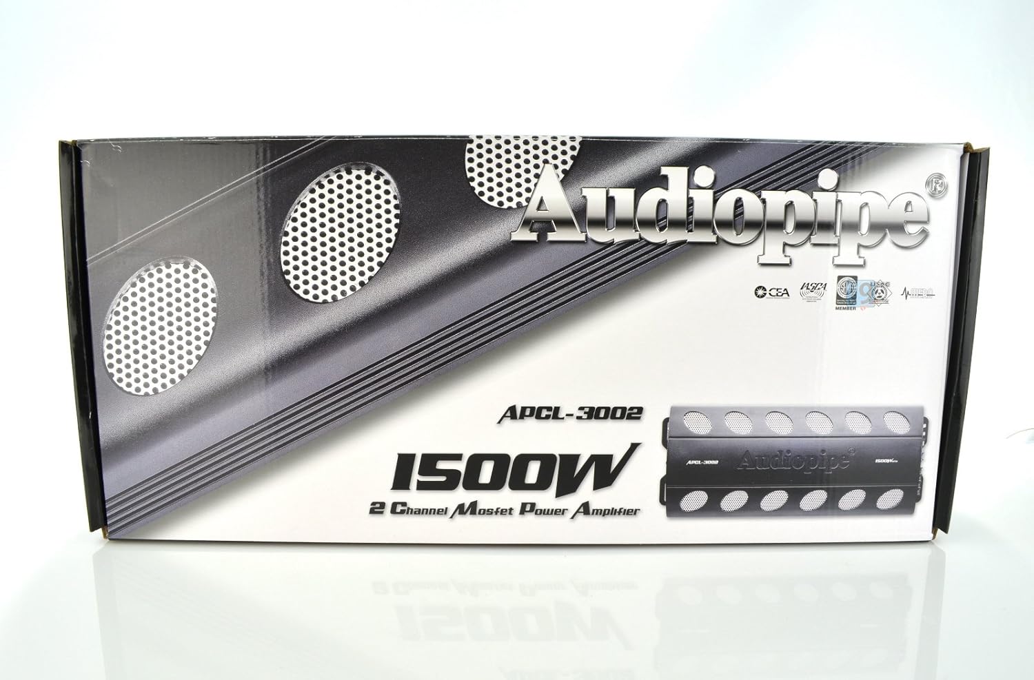
Image: Product Packaging. This image displays the retail box for the Audiopipe APCL3002 amplifier. The packaging features the Audiopipe logo, model number APCL-3002, and highlights its '1500W 2 Channel Mosfet Power Amplifier' specification. Design elements include metallic accents and cooling vent graphics.
Setup and Installation
Mounting Location
Choose a dry, well-ventilated location for mounting the amplifier. Avoid areas exposed to direct sunlight, excessive heat, or moisture. Ensure sufficient space around the amplifier for air circulation, especially around the cooling fan and fins.
Wiring Connections
- Disconnect Battery: Before making any connections, disconnect the vehicle's negative battery terminal.
- Power (BATT +12V): Connect a heavy-gauge power cable (e.g., 4-gauge or 8-gauge, depending on total system power) directly from the vehicle's positive battery terminal to the +12V terminal on the amplifier. Install an in-line fuse holder with a fuse (rated appropriately for your power cable and amplifier) within 18 inches (45 cm) of the battery.
- Ground (GND): Connect a heavy-gauge ground cable of the same size as the power cable from the GND terminal on the amplifier to a clean, unpainted metal surface on the vehicle's chassis. Ensure a good electrical connection by scraping away any paint or rust. The ground cable should be as short as possible.
- Remote Turn-On (REM): Connect a remote turn-on wire (typically 18-gauge) from your head unit's remote output to the REM terminal on the amplifier. This wire signals the amplifier to turn on and off with your head unit.
- RCA Input: Connect RCA cables from your head unit's pre-amp outputs to the RCA INPUT jacks (L and R) on the amplifier.
- Speaker Output: Connect your speakers to the SPEAKER OUTPUT terminals. For 2-channel operation, connect one speaker to the LEFT (+) and (-) terminals and another speaker to the RIGHT (+) and (-) terminals. For bridged mono operation, connect a single subwoofer to the BRIDGED (4Ω MIN) terminals, ensuring the subwoofer impedance is 4 ohms minimum. Observe correct polarity (+ to + and - to -).
- Remote Bass Control: If using the included remote bass control, connect its cable to the designated port on the amplifier.
- Reconnect Battery: Once all connections are secure and verified, reconnect the vehicle's negative battery terminal.
Operating Instructions
Initial Setup and Adjustments
- Gain Control: Start with the GAIN control set to minimum (counter-clockwise). Play a dynamic piece of music at about 75% of your head unit's maximum volume. Slowly increase the GAIN control on the amplifier until you hear distortion, then back it off slightly until the sound is clear. This sets the input sensitivity to match your head unit's output.
- Mode Switch: Select the appropriate mode:
- STEREO: For driving two full-range speakers or components.
- BRIDGED MONO: For driving a single subwoofer with increased power. Ensure the subwoofer's impedance is 4 ohms minimum.
- Filter (Crossover) Settings: Use the FILTER switch to select the desired crossover type:
- LP (Low Pass): Allows only low frequencies to pass through to the speakers/subwoofer. Ideal for subwoofers. Adjust the FREQ knob to set the cutoff frequency (e.g., 80Hz-120Hz).
- HP (High Pass): Allows only high frequencies to pass through. Ideal for full-range or component speakers to prevent them from playing low bass, which can cause distortion. Adjust the FREQ knob to set the cutoff frequency.
- OFF (Full Range): Allows all frequencies to pass through. Use if your head unit or external crossover handles frequency filtering.
- Bass Boost: The BASS BOOST control (0-15dB) can be used to enhance low frequencies. Use sparingly, as excessive bass boost can lead to distortion and potential speaker damage. Adjust the BASS BOOST FREQ knob to select the center frequency for the boost.
- Remote Bass Control: If connected, the remote bass control allows you to adjust the bass level from your listening position without accessing the amplifier directly.
Maintenance
- Cleaning: Periodically clean the amplifier's exterior with a soft, dry cloth. Do not use harsh chemicals or abrasive cleaners.
- Ventilation: Ensure the cooling fan and vents remain free of dust and debris to maintain proper airflow.
- Connections: Periodically check all wiring connections for tightness and corrosion. Loose connections can cause power loss or intermittent operation.
- Fuses: If a fuse blows, replace it only with a fuse of the exact same type and rating (25A MAX). Never use a higher-rated fuse, as this can lead to serious damage or fire.
Troubleshooting
| Problem | Possible Cause | Solution |
|---|---|---|
| No Power / Amplifier Not Turning On |
|
|
| No Sound Output |
|
|
| Distorted Sound |
|
|
| Amplifier Overheating |
|
|
Specifications
- Model: APCL3002
- Type: 2 Channel Amplifier
- Power Output: 1500 Watts (Peak)
- Product Dimensions: 19 x 9 x 4 inches
- Item Weight: 9.4 pounds
- Fuses: 2 x 25A MAX
- Input Sensitivity: Adjustable (typically 0.2V - 6V)
- Crossover: Low Pass Filter (LPF), High Pass Filter (HPF), Full Range (OFF)
- Bass Boost: Adjustable (0-15dB) with frequency control
- Minimum Bridged Impedance: 4 Ohms
Warranty and Support
Audiopipe products are designed for reliability and performance. For specific warranty details, please refer to the warranty card included with your product or contact Audiopipe customer support. Keep your purchase receipt as proof of purchase for any warranty claims.
For technical assistance or support, please visit the official Audiopipe website or contact their customer service department. Ensure you have your model number (APCL3002) and purchase information ready when seeking support.


