
1. Product Overview
The Ideal Industries VDV Multimedia Cable Tester (Model 33-856) is an LCD-based, all-in-one device designed for verifying the proper wiring of low-voltage and data communications cables. Its primary function is to perform wiremap tests, visually indicating pin-by-pin termination and continuity for various cable types.
This tester supports Data/Ethernet (RJ-45), Voice/Phone (RJ-11/12), and Video/Coax cables. The integrated LCD screen clearly displays "PASS" or "ERROR" results after each test, ensuring correct cable termination. It also features a built-in analog tone generator with four user-selectable tones, aiding in cable identification within bundles.

Figure 1: Front view of the VDV Multimedia Cable Tester.
2. Included Components
The VDV Multimedia Cable Tester package includes the following items:
- 1x VDV Multimedia Voice, Data, and Video Wiremapper and Tester (Model 33-856)
- 1x Built-in Remote (Remote #1)
- Instruction Manual
- 1x 9V Battery (may be included or sold separately, refer to packaging)
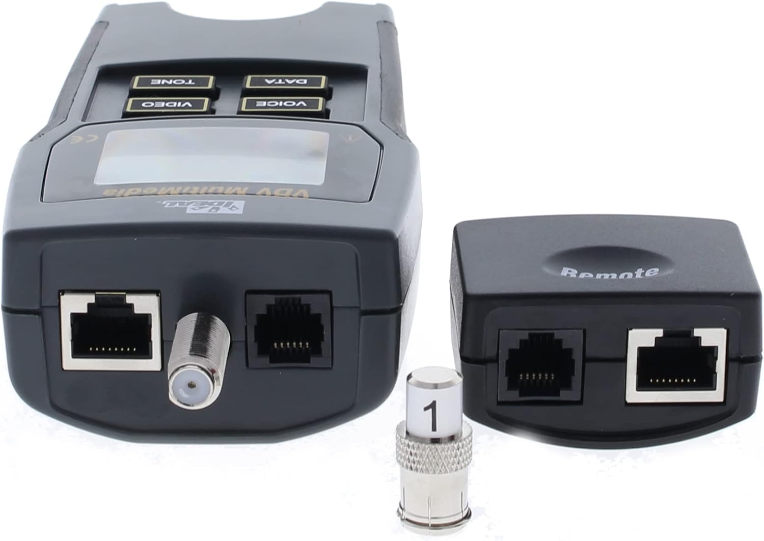
Figure 2: VDV Multimedia Cable Tester main unit, remote, and F-connector adapter.
3. Setup
3.1 Battery Installation
The VDV Multimedia Cable Tester requires one 9V alkaline battery for operation. To install or replace the battery:
- Locate the battery compartment on the back of the tester.
- Using a small Phillips head screwdriver, loosen the screw securing the battery compartment cover.
- Remove the cover.
- Connect a new 9V battery to the battery clip, ensuring correct polarity.
- Place the battery into the compartment and replace the cover, securing it with the screw.

Figure 3: Rear view of the tester with the battery compartment visible.
4. Operating Instructions
4.1 Power On/Off
- To Power On: Press any of the mode buttons (VOICE, VIDEO, DATA, TONE). The LCD will illuminate.
- To Power Off: Press any mode button that is different from the currently active test mode. For example, if in DATA mode, press VOICE, VIDEO, or TONE to turn off the unit. The tester will automatically power off after a period of inactivity to conserve battery life.
4.2 Wiremap Testing
The VDV Multimedia Cable Tester performs wiremap tests to verify proper cable termination and continuity. For all wiremap tests, the main remote unit (Remote #1) must be connected to the far end of the cable run.
4.2.1 Data Cable Testing (RJ-45)
This mode tests RJ-45 connector cables terminated to CAT3/5/5e/6/6a twisted pair cables.
- Connect one end of the data cable to the RJ-45 port on the main tester unit.
- Connect the other end of the data cable to the RJ-45 port on the remote unit.
- Press the DATA button on the main unit.
- The LCD will display the wiremap in a pin-to-pin format and indicate "PASS" or "ERROR". It checks for opens, shorts, miswires, reversals, split pairs, and shield continuity.

Figure 4: Data cable connected to the tester for wiremap verification.
4.2.2 Voice/Phone Cable Testing (RJ-11/12)
This mode tests RJ-11/12 cables, supporting up to 6 conductors.
- Connect one end of the phone cable to the RJ-11/12 port on the main tester unit.
- Connect the other end of the phone cable to the RJ-11/12 port on the remote unit.
- Press the VOICE button on the main unit.
- The LCD will display the wiremap and indicate "PASS" or "ERROR".

Figure 5: Phone cable connected to the tester for wiremap verification.
4.2.3 Video/Coax Cable Testing (F-Connector)
This mode tests coax cables (RG59/6/6 Quad) for opens and shorts on the pin and shield.
- Connect one end of the coax cable to the F-connector port on the main tester unit.
- Connect the other end of the coax cable to the F-connector port on the remote unit.
- Press the VIDEO button on the main unit.
- The LCD will display the test results and indicate "PASS" or "ERROR".

Figure 6: Coax cable connected to the tester for continuity verification.
4.3 Tone Generation
The built-in analog tone generator helps to locate and identify a single cable within a bundle. It can be used in all testing modes.
- Connect the cable to be toned to the main tester unit.
- Press the TONE button.
- Use the VOICE, VIDEO, or DATA buttons to cycle through the four user-selectable tones.
- The tone generator can tone by pin, by pair, or all conductors at once, allowing for precise location of errors like opens.
- For best results in tracing, an Amplifier Probe (Cat # 62-164, sold separately) is recommended to amplify the tone signal.
Video 1: Official product video demonstrating the use of the VDV Multimedia Cable Tester for wiremap testing and tone generation. This video provides a visual guide to the tester's functions and how to interpret results.
5. Maintenance
5.1 Cleaning
To ensure optimal performance and longevity of your tester:
- Wipe the unit with a soft, damp cloth. Do not use abrasive cleaners or solvents.
- Ensure all ports are free of dust and debris. Use compressed air if necessary, but avoid direct contact with sensitive components.
5.2 Battery Replacement
Replace the 9V battery when the low battery indicator appears on the LCD screen or if the unit fails to power on. Refer to Section 3.1 for detailed battery installation instructions.
5.3 Storage
Store the tester in a cool, dry place away from direct sunlight and extreme temperatures. If storing for extended periods, remove the battery to prevent leakage.
6. Troubleshooting
6.1 Common Issues and Solutions
- Tester does not power on: Check battery installation and ensure the 9V battery is fresh.
- "ERROR" displayed during wiremap test: This indicates a wiring fault (open, short, miswire, reversal, or split pair). Inspect the cable and connectors for damage or incorrect termination.
- No tone detected: Ensure the tone generator is active and set to the correct mode. Verify the Amplifier Probe (if used) is functioning and correctly positioned.
- Inconsistent readings: Ensure all cable connections are secure and clean. Test with a known good cable to verify tester functionality.
7. Specifications
| Feature | Specification |
|---|---|
| Brand | Ideal Industries |
| Model Number | 33-856 |
| Item Model Number (Manufacturer) | T39151 |
| Power Source | Hand_powered (requires 9V battery) |
| Supported Cable Types | Data (RJ-45: CAT3/5/5e/6/6a), Voice (RJ-11/12), Video (F-connector: RG59/6/6 Quad) |
| Test Functions | Wiremap (opens, shorts, miswires, reversals, split pairs, shield continuity), Tone Generation |
| Display | LCD |
| Item Weight | 0.78 Pounds (approx. 12.5 ounces) |
| Product Dimensions (L x W x H) | 1 x 1 x 1 inches (approx. 3" W x 2" L x 5" H) |
8. Warranty
Based on the provided information, this product is sold with "No Warranty". Please refer to the retailer's return policy or contact Ideal Industries directly for any specific warranty inquiries.
9. Support
For technical assistance, product information, or service, please contact Ideal Industries directly or visit their official website. Contact information may also be available on the product packaging.
Manufacturer: IDEAL(R)
UPC: 0783250585359