
1. Introduction
The Lutron MO-2002 Electronic Milliohm Meter is a precision instrument designed for accurate measurement of very low resistance. It is ideal for measuring the resistance of components precisely and features a large 20 mm LED display for clear readings. This device includes built-in over input protection to ensure durability and reliable performance.
Key Features:
- Terminal Devices for Accurate Measurement of Very Low Resistance.
- Ideal for Measuring the Resistance of Components Precisely.
- 20 mm, Large Size LED Display.
- Built-in Over Input Protection.
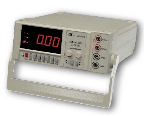
Figure 1.1: Front view of the Lutron MO-2002 Electronic Milliohm Meter.
2. Package Contents
Upon unpacking, please verify that all items listed below are present and undamaged:
- Lutron MO-2002 Electronic Milliohm Meter Unit
- Test Leads (typically four-wire Kelvin clips for accurate low resistance measurements)
- Power Cord
- User Manual (this document)
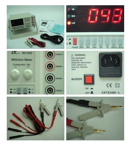
Figure 2.1: The Lutron MO-2002 Milliohm Meter shown with its standard accessories, including test leads and power cable.
3. Product Overview
Familiarize yourself with the various components and controls of the MO-2002 meter.
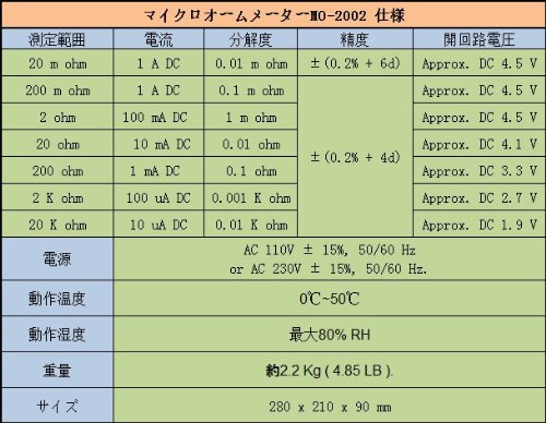
Figure 3.1: Detailed views of the Lutron MO-2002 Milliohm Meter. This composite image displays:
- Top-right: A close-up of the large LED display, showing a reading of "098" along with "HI", "GO", and "LO" indicators, which are used for comparator functions.
- Middle-left: A detailed view of the front panel controls, including the "Comparator Set" knobs for "LO" and "HI" limits, and the four-wire input terminals labeled "FORCE" and "SENSE" for precise resistance measurements.
- Middle-right: The rear panel, featuring the AC power input socket, a buzzer, and the main power ON/OFF switch.
- Bottom-left & Bottom-right: Various types of test leads and Kelvin clips, illustrating the connection options for different measurement scenarios.
Front Panel Controls and Indicators:
- LED Display: Large 20 mm display for resistance readings.
- HI/GO/LO Indicators: LEDs indicating if the measured resistance is High, within tolerance (Go), or Low, based on comparator settings.
- Range Selection Buttons: Buttons to select the desired measurement range (e.g., 20 mΩ, 200 mΩ, 2 Ω, 20 Ω, 200 Ω, 2 KΩ, 20 KΩ).
- Comparator Set Knobs (LO/HI): Rotary knobs to set the lower and upper limits for the comparator function.
- FORCE Terminals: Current injection terminals for the four-wire measurement method.
- SENSE Terminals: Voltage sensing terminals for the four-wire measurement method.
Rear Panel:
- AC Power Input: Socket for connecting the power cord.
- Buzzer: Audible indicator, often used with the comparator function.
- Power ON/OFF Switch: Main power control for the unit.
4. Setup
4.1 Power Connection
- Ensure the MO-2002 is placed on a stable, level surface.
- Verify that the power switch on the rear panel is in the OFF position.
- Connect the provided AC power cord to the power input socket on the rear panel of the meter.
- Plug the other end of the power cord into a suitable AC power outlet (refer to specifications for voltage requirements).
4.2 Connecting Test Leads
The MO-2002 uses a four-wire (Kelvin) measurement method to eliminate the resistance of the test leads from the measurement, ensuring high accuracy for low resistance values.
- Identify the four terminals on the front panel: two "FORCE" terminals and two "SENSE" terminals.
- Connect the test leads (typically Kelvin clips) to the corresponding terminals. Ensure proper polarity if specified by the leads or application. Generally, the two "FORCE" leads carry the test current, and the two "SENSE" leads measure the voltage drop across the resistance under test.
- Ensure all connections are secure to prevent erroneous readings.
5. Operation
5.1 Basic Resistance Measurement
- Turn on the meter by flipping the power switch on the rear panel to the ON position. The LED display will illuminate.
- Select the appropriate measurement range using the range selection buttons on the front panel. Start with a higher range if the resistance value is unknown, then decrease the range for better resolution.
- Connect the Kelvin clips of the test leads to the component or material whose resistance you wish to measure. Ensure good contact.
- Read the resistance value directly from the large LED display.
- If the display shows "OL" (Overload) or "1", select a higher range. If it shows "0" or very low unstable readings, select a lower range.
5.2 Using the Comparator Function
The comparator function allows for quick sorting of components based on predefined resistance limits (HI and LO).
- Set the desired upper (HI) and lower (LO) resistance limits using the "Comparator Set" knobs on the front panel. You may need to use a known good component or a precision resistor to calibrate these settings.
- Connect the component to be tested.
- Observe the HI, GO, and LO indicator LEDs:
- HI LED: Illuminates if the measured resistance is above the set HI limit.
- GO LED: Illuminates if the measured resistance is between the set LO and HI limits (inclusive).
- LO LED: Illuminates if the measured resistance is below the set LO limit.
- The buzzer may also sound depending on the setting, indicating a GO or NO-GO condition.
6. Maintenance
6.1 Cleaning
- Always turn off and disconnect the meter from the power source before cleaning.
- Wipe the exterior of the meter with a soft, damp cloth. Do not use abrasive cleaners or solvents.
- Ensure no liquid enters the meter casing.
6.2 Storage
- Store the meter in a cool, dry place, away from direct sunlight and extreme temperatures.
- If storing for extended periods, ensure the unit is clean and all accessories are neatly stored.
6.3 Calibration
For continued accuracy, periodic calibration by qualified personnel is recommended. Refer to Lutron's official support channels for calibration services.
7. Troubleshooting
| Problem | Possible Cause | Solution |
|---|---|---|
| Meter does not power on. | No power supply; power cord loose; power switch off. | Check power outlet; ensure power cord is securely connected; turn power switch ON. |
| Display shows "OL" or "1". | Resistance value exceeds current range; open circuit. | Select a higher measurement range; ensure test leads are properly connected to the component. |
| Display shows unstable or zero readings. | Poor contact with component; incorrect range selected; short circuit. | Ensure firm contact of test leads; select a lower measurement range; check for short circuits in the component or leads. |
| Comparator LEDs (HI/GO/LO) not functioning as expected. | Comparator limits incorrectly set. | Re-adjust the LO and HI comparator set knobs using a known resistance value. |
If the problem persists after attempting these solutions, please contact Lutron customer support or a qualified service technician.
8. Specifications
| Specification | Value |
|---|---|
| Brand | Lutron |
| Model Number | MO-2002 |
| Measurement Type | Ohmmeter (Milliohm Meter) |
| Power Source | AC Powered (110V/230V, 50/60 Hz) |
| Item Weight | 300 Grams (approx. 0.66 lbs) |
| Product Dimensions (L x W x H) | 28 x 21 x 9 Centimeters (approx. 11 x 8.3 x 3.5 inches) |
| Display | 20 mm Large Size LED Display |
| Included Components | Milliohm Meter |
| Manufacturer | LUTRON ELECTRONIC, LUTRON ELECTRONIC ENTERPRISE CO., LTD, 4F, 106, Min Chuan West Road, 103 Taipei, Taiwan |
| Date First Available | 24 November 2020 |
| Net Quantity | 1 Piece |
| Generic Name | Milliohm Meter |
Note on Power Source: While some specifications might list "Battery Powered", the physical unit and detailed specifications indicate primary operation via AC power, as shown by the AC input socket on the rear panel. Always use the provided AC adapter for operation.
9. Warranty and Support
Lutron products are manufactured to high quality standards. For specific warranty terms and conditions, please refer to the warranty card included with your product or visit the official Lutron website. Keep your purchase receipt as proof of purchase for any warranty claims.
Customer Support:
For technical assistance, troubleshooting beyond this manual, or service inquiries, please contact Lutron customer support. Contact information can typically be found on the manufacturer's website or on the product packaging.
You can find more information about Lutron and their products at their official website: www.lutron.com (Note: This is a generic link for Lutron. Please refer to your product documentation for region-specific support contacts.)