1. Introduction
This manual provides detailed instructions for the proper installation, operation, and maintenance of the Browning Tram BR1010 UHF NMO 3/4-Inch Hole Mount with Preinstalled UHF Male PL-259 Connector. Please read this manual thoroughly before installation to ensure correct setup and optimal performance.
2. Product Features
The Browning Tram BR1010 is engineered for reliable communication system connections. Key features include:
- Solid Brass Mount with Gold Contact Pin: Ensures reliable connectivity and durability.
- Seventeen-Foot RG58A/U Cable: Features 95% tinned copper braid and a stranded tinned copper center conductor for excellent signal quality.
- Preinstalled UHF Male PL-259 Connector: Comes with strain relief for a secure and stable connection.
- Low Loss to 1,000 MHz: Minimizes signal loss for optimal performance across a wide frequency range.
- High-Quality Construction: Designed for long-lasting use and reliable signal transmission.
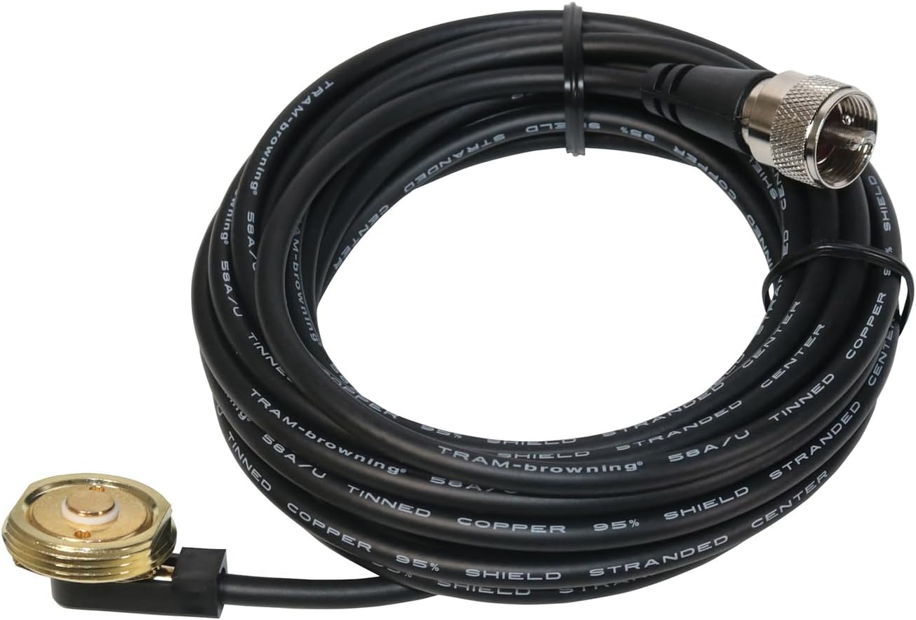
Figure 1: Overview of the Browning Tram BR1010 NMO Hole Mount, showing the NMO base, the coiled RG58A/U coaxial cable, and the preinstalled UHF Male PL-259 connector.
3. Safety Information
Observe the following safety precautions during installation and use:
- Ensure the vehicle or mounting surface is clean and dry before drilling.
- Always disconnect the vehicle's battery before performing any electrical work to prevent short circuits.
- Wear appropriate personal protective equipment, such as safety glasses, when drilling.
- Verify the drilling location does not interfere with existing wiring, fuel lines, or other critical components.
- Route the coaxial cable away from hot engine parts, sharp edges, and moving components to prevent damage.
4. Setup and Installation
The Browning Tram BR1010 is designed for a 3/4-inch NMO hole mount installation. Follow these steps carefully:
4.1 Required Tools
- 3/4-inch hole saw or drill bit
- Drill
- Deburring tool or file
- Wrench (for NMO nut)
- Sealant (optional, for added weather protection)
4.2 Mounting Location Selection
Choose a flat, sturdy surface for mounting, such as a vehicle roof or trunk lid, ensuring sufficient clearance for the antenna (not included) and cable routing. Avoid areas with excessive curvature or obstructions.
4.3 Drilling the Hole
- Mark the exact center of your chosen mounting location.
- Carefully drill a 3/4-inch hole through the mounting surface.
- Deburr the edges of the hole to remove any sharp metal fragments that could damage the cable or compromise the seal.
- Clean the area around the hole thoroughly.
4.4 Installing the NMO Mount
- From the underside of the mounting surface, feed the coaxial cable through the drilled hole.
- Position the NMO mount base (the part with the gold contact pin) into the hole from the top side of the mounting surface. Ensure the rubber gasket is properly seated to create a watertight seal.
- From the underside, thread the large NMO nut onto the mount. Tighten the nut securely with a wrench, but do not overtighten, as this can damage the mount or the mounting surface.

Figure 2: Top view of the NMO mount base, showing the gold contact pin and threaded exterior for antenna attachment.

Figure 3: Bottom view of the NMO mount base, illustrating the cable connection point and the securing nut threads.
4.5 Cable Routing
Route the 17-foot RG58A/U coaxial cable from the NMO mount to your radio equipment. Ensure the cable is:
- Secured to prevent movement and chafing.
- Protected from heat sources, sharp edges, and areas where it could be pinched or cut.
- Routed to avoid interference with vehicle operations (e.g., pedals, steering column).
4.6 Connecting to Radio Equipment
The cable is terminated with a preinstalled UHF Male PL-259 connector. Connect this connector to the corresponding UHF Female (SO-239) port on your radio or antenna tuner. Ensure the connection is finger-tight, then use a wrench to gently snug it, avoiding overtightening.
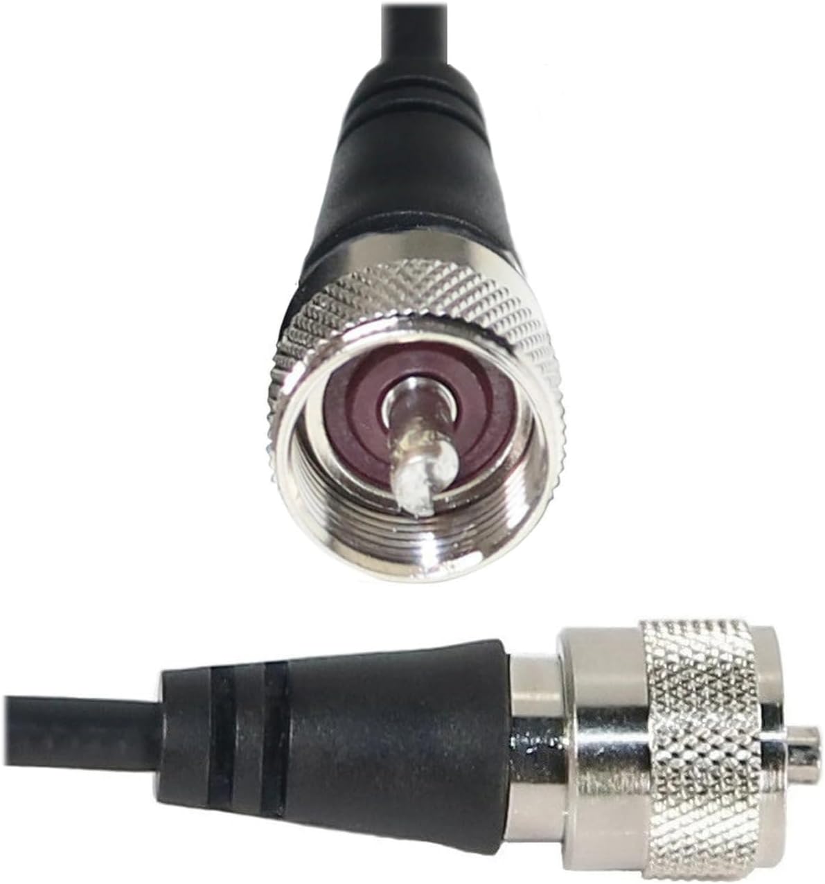
Figure 4: Detailed view of the UHF Male PL-259 connector, showing the threaded barrel and center pin.
5. Operation
Once the Browning Tram BR1010 NMO mount and cable are correctly installed and connected to your antenna (not included) and radio equipment, its operation is passive. The mount and cable facilitate the transmission and reception of radio signals. Ensure all connections remain secure for optimal performance.
6. Maintenance
Regular maintenance helps ensure the longevity and performance of your NMO mount and cable:
- Periodic Inspection: Annually inspect the NMO mount for signs of corrosion, wear, or damage to the rubber gasket. Check the cable for cuts, kinks, or fraying, especially where it enters the vehicle or passes through tight spaces.
- Connection Check: Periodically verify that the NMO nut and the PL-259 connector are securely tightened.
- Cleaning: Keep the NMO mount and connector clean from dirt, dust, and moisture. Use a soft, dry cloth. Avoid abrasive cleaners or solvents.
7. Troubleshooting
If you experience issues with your communication system, consider the following:
| Problem | Possible Cause | Solution |
|---|---|---|
| Poor signal quality or high SWR | Loose connections, damaged cable, improper antenna tuning, corrosion on contacts. | Check all connections (NMO mount to antenna, PL-259 to radio). Inspect the cable for damage. Ensure the antenna is properly tuned for the operating frequency. Clean contacts if corrosion is present. |
| Water leakage around mount | Improperly seated gasket, loose NMO nut, damaged gasket. | Ensure the rubber gasket is correctly positioned. Tighten the NMO nut. Replace the gasket if it is damaged. Consider applying a marine-grade sealant around the mount base. |
| No signal transmission/reception | Disconnected cable, faulty radio equipment, antenna issue. | Verify the PL-259 connector is fully seated in the radio. Test the radio with a known good antenna/cable setup. Inspect the antenna for damage. |
8. Specifications
| Attribute | Detail |
|---|---|
| Brand | Browning |
| Model Name | Browning BR1010 - UHF NMO 3/4" Hole Mount |
| Item Model Number | WSPBR1010 |
| Connector Type | UHF Male PL-259 (preinstalled) |
| Cable Type | RG58A/U Coaxial |
| Cable Length | 17 feet (approx. 5.18 meters) |
| Cable Braid | 95% Tinned Copper Braid |
| Center Conductor | Stranded Tinned Copper |
| Mount Type | NMO 3/4-inch Hole Mount |
| Mount Material | Solid Brass with Gold Contact Pin |
| Frequency Range | Low Loss to 1,000 MHz |
| Color | Black |
| Item Weight | 9.6 ounces (approx. 272 grams) |
| Product Dimensions | 6.5 x 6.1 x 1.25 inches (packaging) |
| Recommended Uses | Mobile and Marine Communication Systems |
| Indoor/Outdoor Usage | Outdoor |
| UPC | 727932012481 |
9. Warranty Information
Specific warranty details for the Browning Tram BR1010 are provided by the manufacturer. Please refer to the product packaging or contact Browning directly for comprehensive warranty terms and conditions.
10. Customer Support
For technical assistance, troubleshooting beyond this manual, or warranty inquiries, please contact Browning customer support. Contact information can typically be found on the product packaging or the official Browning website.
Manufacturer: Browning
Website: www.trambrowning.com


