Introduction
This manual provides instructions for the proper installation, operation, and maintenance of your MFJ-1778M G5RV Junior Wire Antenna. Please read this manual thoroughly before proceeding with installation to ensure safe and effective use of the antenna.
Product Overview
The MFJ-1778M is a multi-band, center-fed dipole wire antenna designed for amateur radio operation. It is capable of handling up to 1500 Watts of power. The antenna consists of a 52-foot flat-top radiating element, fed by a 17-foot section of 450 Ohm matching ladder line, which terminates in an SO-239 coaxial connector. This design allows for operation across the 40, 20, 15, and 10 meter bands, and often with an antenna tuner, on 80 meters as well.
Safety Information
- Power Lines: Never install the antenna near power lines. Contact with power lines can be fatal. Maintain a safe distance from all electrical wires.
- Height: Install the antenna at a height where it cannot be accidentally touched by people or animals.
- Weather: Avoid installing or adjusting the antenna during thunderstorms or high winds.
- Grounding: Ensure proper grounding of your radio equipment and antenna system according to local electrical codes to protect against lightning and static discharge.
- RF Exposure: Operate the antenna within safe RF exposure limits. Consult relevant guidelines for your power level and operating frequencies.
Package Contents
Verify that all components are present and undamaged upon unpacking:
- MFJ-1778M G5RV Junior Wire Antenna (52 ft flat-top element)
- 17 ft 450 Ohm Matching Ladder Line with SO-239 Connector
- Insulators (typically two end insulators and one center insulator/feedpoint)
- Instruction Manual
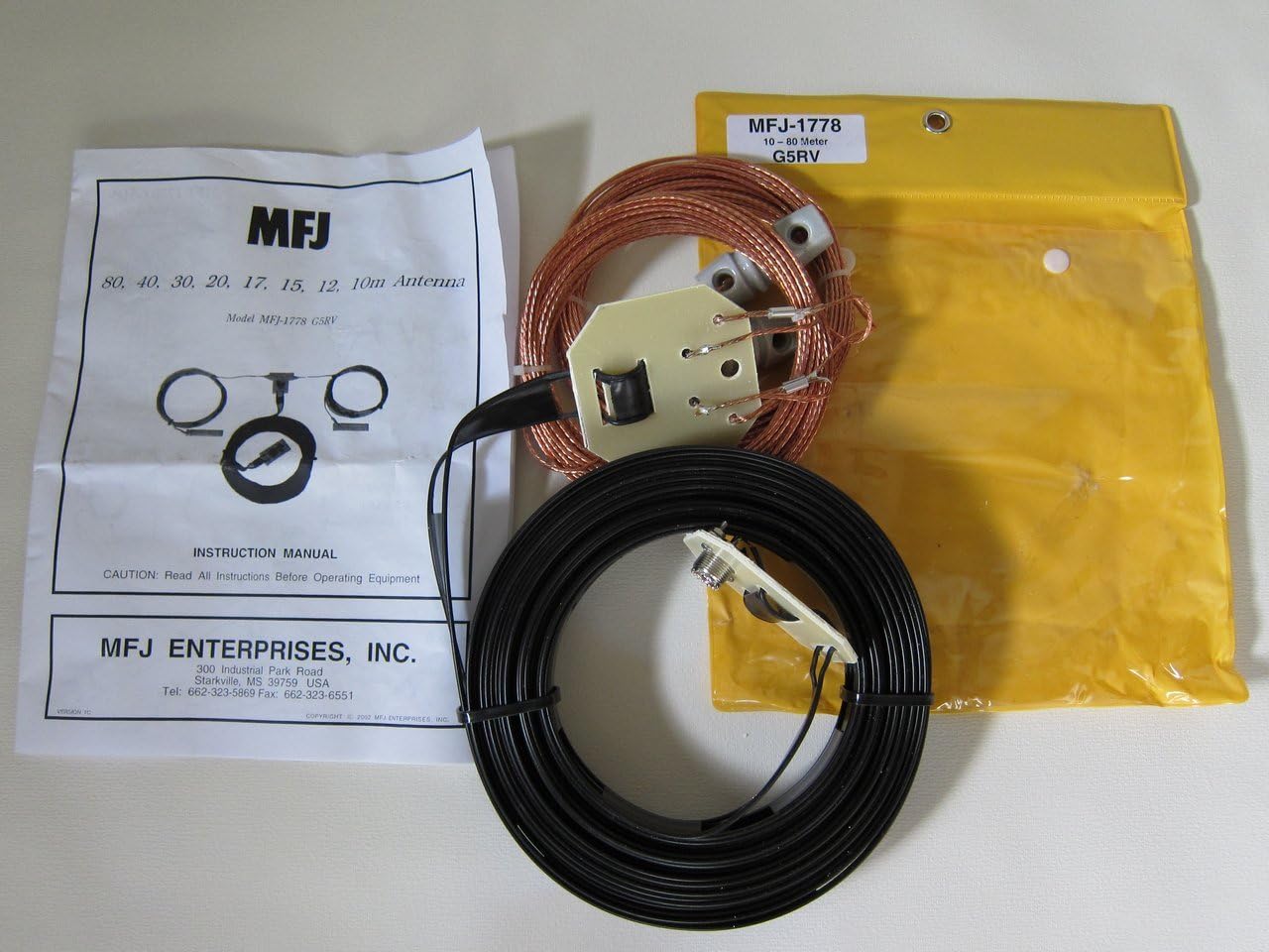
Image: Contents of the MFJ-1778M G5RV Junior Wire Antenna package, showing the coiled wire elements, the matching section with SO-239 connector, and the printed instruction manual.

Image: A closer view of the MFJ-1778M G5RV Junior antenna components, highlighting the coiled wire elements, the 450 Ohm ladder line, and the grey end insulators.
Setup
- Location Selection: Choose an installation site that is as high and clear as possible, away from power lines, metal objects, and buildings. The G5RV Junior performs best when installed as a horizontal dipole or an inverted-V.
- Antenna Configuration:
- Horizontal Dipole: Suspend the 52-foot flat-top element horizontally between two support points. The center feedpoint should be at the highest point.
- Inverted-V: Elevate the center feedpoint as high as possible, then allow the two ends of the 52-foot element to slope downwards. The angle between the two legs should ideally be between 90 and 120 degrees. The ends should be at least 10 feet off the ground.
- Mounting the Antenna: Use strong, non-conductive rope (e.g., Dacron or nylon) to support the antenna. Attach the rope to the end insulators and the center feedpoint. Ensure the antenna is taut but not excessively stressed.
- Ladder Line Routing: The 17-foot 450 Ohm ladder line should hang vertically downwards from the center feedpoint for at least the first few feet before being routed to your operating position. Avoid running the ladder line parallel to large metal objects or directly along the ground.
- Coaxial Cable Connection: Connect a 50 Ohm coaxial cable (e.g., RG-8X, RG-213) to the SO-239 connector at the end of the ladder line. Ensure the connection is secure and weatherproofed.
- Grounding: Connect the shield of your coaxial cable to a good station ground. This is crucial for safety and performance.
Operating Instructions
- Connect to Transceiver: Connect the coaxial cable from the antenna to your transceiver's antenna input.
- Antenna Tuner: The G5RV Junior antenna typically requires an external antenna tuner for optimal performance across all bands (40, 20, 15, 10 meters, and especially 80 meters). Connect the antenna tuner between the transceiver and the antenna.
- SWR Measurement: Before transmitting, always check the Standing Wave Ratio (SWR) using your transceiver's built-in SWR meter or an external SWR meter. Adjust your antenna tuner for the lowest possible SWR (ideally 1.5:1 or lower) on your desired operating frequency.
- Power Output: The MFJ-1778M is rated for up to 1500 Watts. However, always start with low power when tuning and ensure SWR is acceptable before increasing power.
- Band Selection: The antenna is designed for multi-band operation. Use your tuner to achieve resonance on the desired band.
Maintenance
- Regular Inspection: Periodically inspect the antenna wire, ladder line, insulators, and coaxial connections for wear, damage, or corrosion. Pay close attention to solder joints at the feedpoint.
- Weatherproofing: Ensure all coaxial connections are properly weatherproofed using self-amalgamating tape or other suitable methods to prevent moisture ingress.
- Cleanliness: Keep the antenna elements free from debris, ice, or heavy snow, which can affect performance and structural integrity.
- Support Ropes: Check the condition of support ropes and replace them if they show signs of fraying or degradation from UV exposure.
Troubleshooting
| Problem | Possible Cause | Solution |
|---|---|---|
| High SWR on all bands |
|
|
| High SWR on specific bands |
|
|
| Poor reception/transmission |
|
|
Specifications
- Model: MFJ-1778M
- Antenna Type: Multi-band Center-fed Dipole Wire Antenna (G5RV Junior)
- Frequency Coverage: 40, 20, 15, 10 Meters (with tuner, often 80 Meters)
- Power Rating: 1500 Watts
- Flat-top Element Length: Approximately 52 feet
- Matching Section: 17 feet of 450 Ohm Ladder Line
- Feedpoint Connector: SO-239
- Overall Dimensions (packaged): 11.26 x 9.69 x 2.44 inches
- Item Weight: 1.32 pounds
Warranty and Support
For warranty information, technical support, or service inquiries regarding your MFJ-1778M G5RV Junior Wire Antenna, please contact MFJ Enterprises, Inc. directly. Refer to the contact information provided with your product packaging or visit the official MFJ website.
Manufacturer: MFJ Enterprises, Inc.


