
Testo 0563 3100
Testo 310 Residential Combustion Analyzer Kit User Manual
Model: 0563 3100 | Brand: Testo
1. Product Overview
The Testo 310 Residential Combustion Analyzer is a robust and reliable instrument designed for comprehensive flue gas analysis, maintenance, safety checks, and efficiency confirmations of residential heating systems. It provides accurate measurements for various parameters crucial for optimal combustion tuning.

Figure 1: Testo 310 Combustion Analyzer handheld device.
2. Scope of Delivery
The Testo 310 kit includes all necessary components for immediate use:
- Testo 310 combustion analyzer
- Sensors
- Probe with cone
- Hose
- Silicon tubing (for pressure)
- 5 x particulate filters
- 5 x pressure plugs
- Calibration certificate
- Hard-shell case

Figure 2: Complete Testo 310 kit contents.
3. Setup
3.1 Initial Charging
The Testo 310 operates on rechargeable lithium-ion batteries. Use the provided charging puck and USB cable to charge the unit. Connect the USB cable to the base of the unit and the charging puck to a power source. It is recommended to use the original charging accessories.
3.2 Powering On and Initial Calibration
To power on the instrument, press and hold the power button for 3 seconds. Upon first startup, the analyzer will prompt you to set up location settings, units of measure (for pressure and temperature), and the time and date. Use the arrow keys to navigate and the 'OK' button to confirm selections. The instrument will also perform a 30-second sensor zeroing feature. Ensure this is done in fresh air, preferably outdoors, for proper calibration.
Video 1: Official guide on how to use the Testo 310 Combustion Analyzer, including initial setup and calibration.
3.3 Probe Connection
Connect the probe to the analyzer using the provided hose. The probe cone allows for proper seating into various flue gas duct sizes. For differential pressure measurements, you may need to attach the silicone tubing to the probe shaft.

Figure 3: Connecting the Testo 310 probe for measurements.
4. Operating Instructions
4.1 User Interface and Controls
The Testo 310 features a clear, backlit display for easy readability. The control panel includes:
- Power Button: Press and hold for 3 seconds to power on/off.
- Backlight Button: Turns on/off the illuminated display for better visibility.
- ESC Button: Returns to the previous screen or the measurement display screen if pressed multiple times.
- Up/Down Arrows: Cycle through measurement values and menu options.
- Print Button: Sends data to an optional Testo IR printer.
- Orange Buttons (Soft Keys): Correspond to the data displayed on the screen directly above them. The center orange button typically acts as 'OK' or 'Start/Stop' for measurements.
4.2 Selecting Measurement Types
The top section of the display shows four symbols corresponding to different measurement tests:
- Flue Gas Test: Standard combustion analysis.
- Ambient CO Test: Measures carbon monoxide in the surrounding environment.
- Draft Measurement: Measures draft pressure.
- Differential Pressure Measurement: Measures pressure differences.
Select these measurements by pressing the left orange button. A black arrow below the icon indicates the selected measurement.
4.3 Performing a Flue Gas Test
Before starting, ensure the correct fuel type (Natural Gas, Propane, Fuel Oil 2, Biomass, Wood) is selected by pressing the right orange button and using the arrow keys to scroll through the list. Confirm with 'OK'. Insert the probe into the flue gas duct. The measurement values for O2 and CO will be displayed. Additional calculated values can be viewed using the up/down arrows.
4.4 Performing an Ambient CO Test
Select the Ambient CO measurement. Press the center orange button to start and stop this measurement. Note that cigarette smoke can influence the measurement value by more than 50 ppm.
4.5 Performing a Draft Measurement
It is crucial to start this test with the flue gas probe outside of the flue. Then, start the measurement using the center orange button. A draft zeroing countdown will appear. Ensure the probe remains still during this countdown for proper zeroing. Once zeroed, insert the probe into the flue to take the measurement.
4.6 Performing a Differential Pressure Measurement
When selecting differential pressure, the screen will display 'PLUG'. This indicates you must remove the yellow cone filter from the back of your probe handle and replace it with the orange plug (conveniently stored in the probe handle). Secure one end of the silicone hose to the probe shaft, ensuring it covers all openings. Then, start the measurement with the 'Start/Stop' selection. The display will count down to zero the pressure reading. Once completed, connect the other end of the silicone hose to your measurement point.
5. Maintenance
5.1 Condensate Trap Emptying
Moisture will collect in the condensate trap from continuous use. The level can be monitored via the view window on the side of the instrument. To empty, pull the condensate plug located on the top of the instrument and drain the liquid. Never let the moisture level reach the max fill line. After emptying, fully seal the condensate plug to prevent air from being pulled into the system, which can lead to measurement errors.
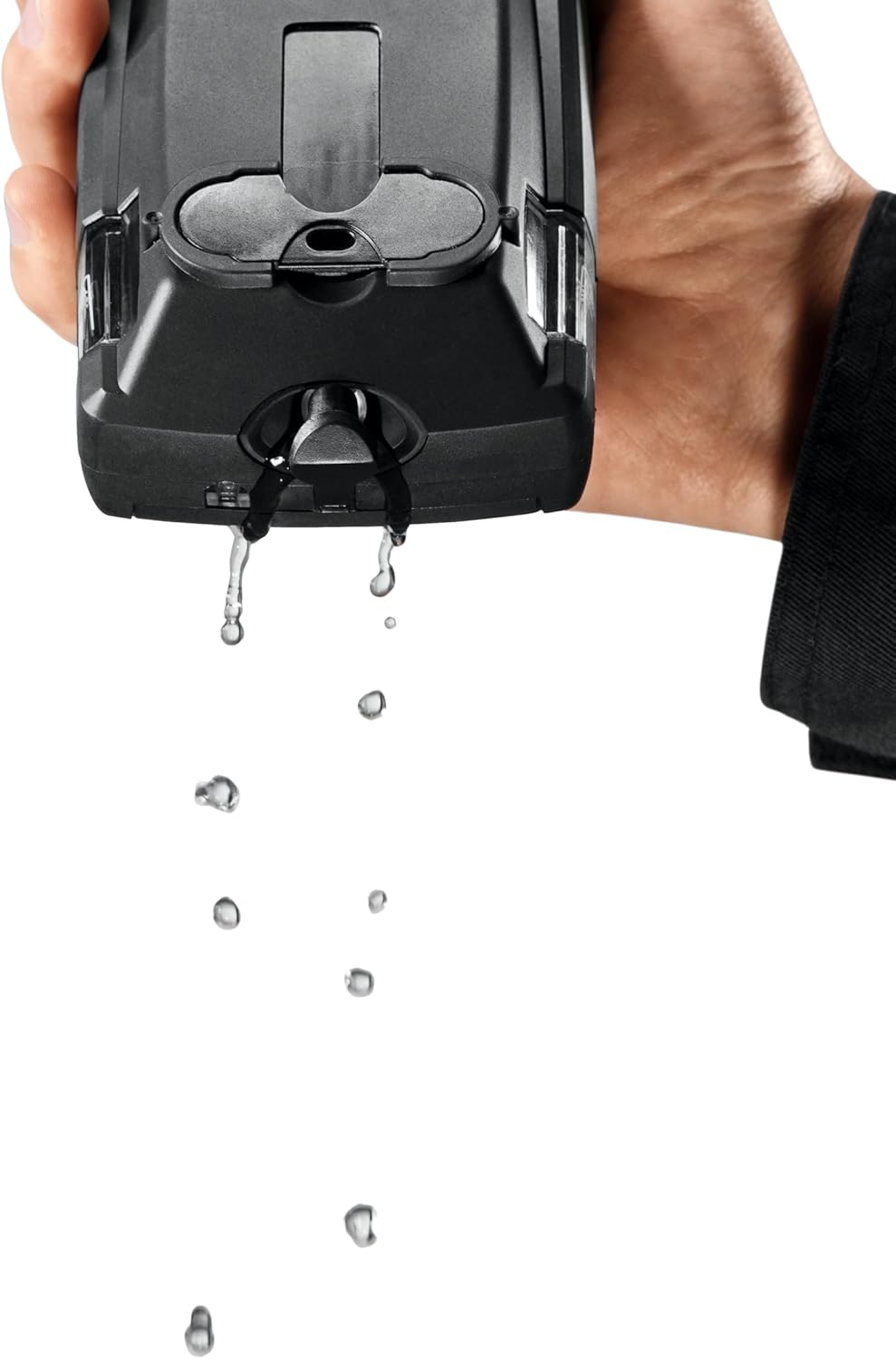
Figure 4: Emptying the condensate trap.
5.2 Filter Replacement
The yellow cone filter in the probe handle should be replaced as needed. Access it by rotating the clear plastic cover counter-clockwise. Replace with a new particulate filter from the kit.
5.3 Storage and Sensor Care
When storing your instrument, avoid excessive hot or cold temperatures. The electrochemical sensors are sensitive to extreme temperatures, which can cause premature wear and shorten their lifespan. If storing for long periods, periodically turn on the instrument and keep the battery charged to prolong sensor life and ensure optimal performance.
6. Troubleshooting
If you encounter issues with your Testo 310, consider the following:
- Inaccurate Readings: Ensure proper calibration was performed in fresh air. Check for blockages in the probe or hoses. Verify the condensate trap is not overfilled and is properly sealed.
- Display Issues: Use the backlight function in dark conditions. If the display is unresponsive, try powering off and on.
- Power Issues: Ensure the battery is fully charged using the provided charger.
- Sensor Errors: Refer to the calibration certificate for sensor lifespan. If errors persist, contact Testo customer support.
7. Technical Specifications
| Parameter | Specification |
|---|---|
| Temperature Measuring Range (K TC) | -4° to 212 °F / -20 to +100 °C |
| Temperature Measurement Accuracy (K TC) | ±2 °F / ±1 °C |
| Temperature Measuring Range (J TC) | 32° to 752 °F / 0 to +400 °C |
| Temperature Measurement Accuracy (J TC) | ±1.8 °F (32° to 212 °F) / ±1 °C (0 to +100 °C); ±1.5 % of mv (> 212 °F) / ±1.5 % of mv (> 100 °C) |
| O2 Measuring Range | 0 to 21 Vol.% |
| O2 Measurement Accuracy | ±0.2 Vol.% |
| Draft Measuring Range | -8 to +8 InH₂O / -20 to +20 hPa |
| Draft Measurement Accuracy | ±0.01 InH₂O (-1.20 to +1.20 InH₂O) / ±0.03 hPa (-3.00 to +3.00 hPa) / ±1.5 % of mv (Remaining Range) |
| Efficiency Measuring Range (Calculated) | 0 to 120 % |
| Flue Gas Loss Measuring Range | 0 to 99.9 % |
| CO2 Calculation Measuring Range | 0 to CO₂ max (Display range) |
| CO2 Calculation Accuracy | ±0.2 Vol.% |
| Pressure Measuring Range | -16 to +16 InH₂O / -40 to +40 hPa |
| Pressure Measurement Accuracy | ±0.2 InH₂O / ±0.5 hPa |
| CO and Ambient CO Measuring Range | 0 to 4000 ppm |
| CO Ambient CO Measurement Accuracy | ±20 ppm (0 to 400 ppm) / ±5 % of mv (401 to 2000 ppm) / ±10 % of mv (2001 to 4000 ppm) |
| Dimensions | 8 x 3 x 2 in. / 201 x 83 x 44 mm |
| Weight (with probe) | Approx. 25 oz. / Approx. 700 g |
| Power Source | Rechargeable Lithium Ion Battery (included) |
8. Warranty and Support
For detailed warranty information and technical support, please refer to the official Testo website or the comprehensive user manual provided in PDF format:
You can also visit the Testo Store on Amazon for additional product information and resources.
Related documents0563 3100


Ask a question about this manual
Ask about setup, troubleshooting, compatibility, parts, safety, or missing instructions. Manuals+ will review the question and use this page’s manual context to help answer it.