Introduction
This manual provides essential information for the proper installation, operation, and maintenance of the Liftmaster MA005 Gear Reducer. The MA005 is a 60:1 ratio gear reducer designed for use with various Liftmaster Mega-Arm and Mega-Tower barrier gate operator models, including MADCBB and MATDCBB. Adhering to these instructions will ensure optimal performance and longevity of the component.
Product Overview
The Liftmaster MA005 Gear Reducer is a critical component in the mechanical drive system of compatible barrier gate operators. It reduces the rotational speed from the motor to the gate arm, providing the necessary torque for smooth and controlled operation. The kit typically includes the gear reducer unit and a mounting bracket with a shaft collar.
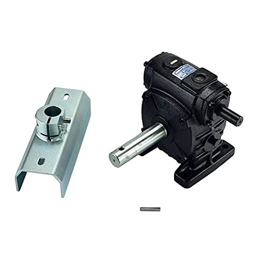
Figure 1: The Liftmaster MA005 Gear Reducer (right) and its accompanying mounting bracket with shaft collar (left). The gear reducer is a black, robust unit with input and output shafts, while the bracket is a galvanized metal channel designed for secure attachment.
Key components include:
- Gear Reducer Unit: The main assembly containing the gears for speed reduction.
- Mounting Bracket: A metal channel for securing the gear reducer to the gate operator frame.
- Shaft Collar: Used to secure the output shaft within the mounting bracket.
- Key/Pin: A small metal pin for securing the shaft to other components.
Setup and Installation
Installation of the MA005 Gear Reducer should be performed by qualified personnel. Always disconnect power to the gate operator before beginning any installation or maintenance procedures.
- Power Disconnection: Ensure the gate operator's main power supply is completely disconnected and locked out to prevent accidental startup.
- Access Existing Unit: Carefully open the gate operator housing to gain access to the existing gear reducer or the mounting location.
- Remove Old Unit (if applicable): If replacing an existing unit, carefully disconnect any shafts, mounting bolts, and electrical connections (if present) from the old gear reducer. Note the orientation for proper installation of the new unit.
- Position New Gear Reducer: Place the new MA005 gear reducer into its designated mounting position within the gate operator frame. Ensure proper alignment with the motor's output shaft and the gate arm's input shaft.
- Secure Mounting Bracket: Attach the mounting bracket to the gate operator frame using appropriate hardware. Ensure it is level and securely fastened.
- Connect Shafts: Slide the input shaft of the gear reducer onto the motor's output shaft and the gate arm's input shaft onto the gear reducer's output shaft. Secure all connections with keys, pins, or set screws as required by the specific gate operator model.
- Tighten Fasteners: Systematically tighten all mounting bolts and shaft fasteners. Do not overtighten, but ensure all components are secure to prevent vibration and misalignment.
- Verify Alignment: Manually rotate the gate arm (if possible) to check for smooth movement and proper alignment of all connected components. There should be no binding or excessive friction.
- Close Housing: Once installation is complete and verified, carefully close and secure the gate operator housing.
- Restore Power: Reconnect the main power supply to the gate operator.
- Test Operation: Perform several test cycles of the gate operator to ensure the gear reducer functions correctly and the gate arm moves smoothly through its full range of motion.
Operating Principles
The MA005 Gear Reducer operates passively as a mechanical component. Its function is to convert the high-speed, low-torque output from the electric motor into a lower-speed, higher-torque output suitable for moving the heavy gate arm. The 60:1 ratio means that for every 60 rotations of the input shaft from the motor, the output shaft connected to the gate arm will rotate once. This reduction in speed and increase in torque is essential for the safe and efficient operation of barrier gates.
The gear reducer is designed for continuous duty within the specified operational parameters of compatible Liftmaster gate operators. It requires no direct user interaction during normal operation.
Maintenance
Regular maintenance is crucial for the longevity and reliable performance of the MA005 Gear Reducer. Always disconnect power before performing maintenance.
- Lubrication: The MA005 is typically a sealed unit and does not require external lubrication. Refer to the specific gate operator's manual for any recommended lubrication points on connected components (e.g., bearings, chains).
- Inspection (Quarterly/Bi-Annually):
- Visually inspect the gear reducer for any signs of oil leaks, cracks, or physical damage.
- Check all mounting bolts and shaft connections for tightness. Retighten if necessary.
- Listen for unusual noises (grinding, whining) during gate operation, which may indicate internal wear.
- Inspect the input and output shafts for excessive play or wobble.
- Cleaning: Keep the exterior of the gear reducer clean and free from excessive dust, dirt, or debris, which can act as insulation and lead to overheating. Use a dry cloth or soft brush.
- Replacement: If significant wear, damage, or excessive noise is detected, the gear reducer should be replaced to prevent further damage to the gate operator system.
Troubleshooting
This section addresses common issues related to the gear reducer. For comprehensive gate operator troubleshooting, refer to the specific operator's manual.
| Symptom | Possible Cause | Solution |
|---|---|---|
| Excessive noise (grinding, whining) from gear reducer area. | Internal gear wear, lack of lubrication (unlikely for sealed unit), bearing failure. | Inspect for leaks. If noise persists and is confirmed from the unit, replacement is likely required. |
| Gate arm moves slowly or struggles. | Gear reducer internal friction/damage, motor issues, gate arm obstruction, incorrect gate balance. | Check for obstructions. Verify motor operation. If gear reducer is hot or binding, it may need replacement. |
| Oil leaks from gear reducer. | Damaged seals, cracked housing. | The unit is sealed; leaks indicate internal damage. Replacement is necessary. |
| Gate arm does not move, but motor runs. | Sheared key/pin on input/output shaft, internal gear failure. | Inspect shaft connections for sheared keys. If connections are intact, the gear reducer has failed internally and requires replacement. |
Specifications
- Model: MA005
- Type: Gear Reducer
- Gear Ratio: 60:1
- Compatibility: Various Liftmaster Mega-Arm and Mega-Tower barrier gate operator models (e.g., MADCBB, MATDCBB)
- Part Number: MA005
- Material: Cast iron/steel housing, hardened steel gears
- Lubrication: Factory-sealed, no external lubrication required
Warranty and Support
For warranty information and technical support regarding the Liftmaster MA005 Gear Reducer, please refer to the documentation provided with your specific Liftmaster barrier gate operator or contact Liftmaster/Chamberlain customer service directly. Warranty terms typically cover manufacturing defects for a specified period from the date of purchase. Proof of purchase may be required for warranty claims.
It is recommended to use only genuine Liftmaster replacement parts to ensure compatibility and maintain product warranty.