1. Introduction
This manual provides essential information for the safe and effective operation, setup, maintenance, and troubleshooting of your Hobart Handler 140 MIG Welder. Please read this manual thoroughly before operating the unit to ensure proper usage and to prevent injury or damage.
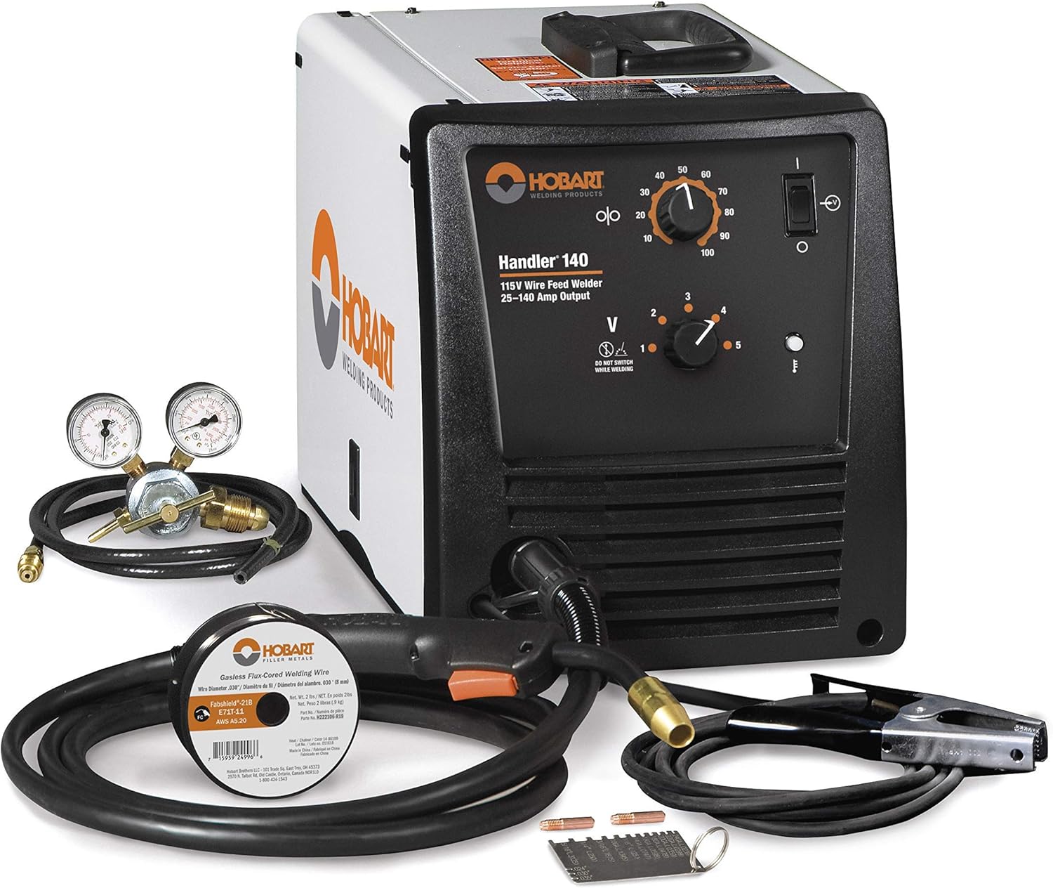
Figure 1.1: The Hobart Handler 140 MIG Welder with included accessories, such as the gas regulator and welding gun.
2. Safety Precautions
WARNING: Read and follow all labels and the Owner's Manual carefully before installing, operating, or servicing this unit. Refer to the Safety Information at the beginning of the manual and in each section.
2.1 Arc Welding Hazards
ELECTRIC SHOCK CAN KILL.
- Always verify the supply ground and check that the input power cord ground wire is properly connected to ground.
- Do not touch live electrical parts. The electrode and work circuit are electrically live whenever the output is on.
- Wear dry, hole-free insulating gloves and body protection.
- Do not use worn, damaged, undersized, or poorly spliced cables.
- Do not drape cables over your body.
FUMES AND GASES CAN BE HAZARDOUS TO YOUR HEALTH.
- Keep your head out of the fumes.
- Use enough ventilation and/or exhaust at the arc to keep fumes and gases away from the breathing zone.
ARC RAYS CAN BURN EYES AND SKIN.
- Wear a welding helmet with a proper shade of filter to protect your face and eyes when welding or watching.
- Wear approved safety glasses with side shields under your helmet.
- Wear body protection made from durable, flame-resistant material.
For a complete list of safety information, consult the full Owner's Manual.
3. Included Components
The Hobart Handler 140 MIG Welder (Model 500559) typically includes the following items:
- Hobart Handler 140 Power Source
- 10 ft. MIG Gun with Liner
- 10 ft. Work Cable with Clamp
- Dual-Gauge Regulator with Gas Hose
- Sample Spool of Flux-Cored Wire (0.030 in.)
- Sample Spool of Solid Wire (0.030 in.)
- Drive Rolls for 0.024/0.030 in. Solid Wire and 0.030/0.035 in. Flux-Cored Wire
- Contact Tips (0.024 in. and 0.030 in.)
- Spool Hub Assembly for 8-inch Spools
- Owner's Manual
4. Setup Instructions
Proper setup is crucial for safe and effective welding. Follow these steps to prepare your Handler 140 for operation.
4.1 Power Connection
The Handler 140 operates on 115V AC power. Ensure you connect the welder to a properly grounded 115V, 20A circuit.
4.2 Wire Spool Installation
- Open the side access door of the welder.
- Install the wire spool onto the spool hub. The Handler 140 supports both 2 lb and 8 lb spools. Use the provided adapter for 8-inch spools if necessary.
- Thread the wire through the drive roll system. Ensure the correct drive roll size is selected for your wire diameter.
- Close the drive roll tension arm. Adjust tension as needed; too much tension can deform the wire, while too little can cause slippage.

Figure 4.1: The internal wire feed mechanism, showing the spool and drive rolls. Proper wire threading and tension are essential.

Figure 4.2: An inside view of the welder, illustrating the placement of the wire spool and the wire path to the drive system.
4.3 Polarity and Gas Connection
The Handler 140 allows for easy polarity changes, which is necessary when switching between flux-cored and solid wire welding.
- Flux-Cored Wire: Use DCEN (Direct Current Electrode Negative). The MIG gun connects to the negative terminal, and the work clamp to the positive terminal. No shielding gas is required.
- Solid Wire (MIG): Use DCEP (Direct Current Electrode Positive). The MIG gun connects to the positive terminal, and the work clamp to the negative terminal. Shielding gas (e.g., C25 or 100% Argon) is required. Connect the provided dual-gauge regulator to your gas cylinder and then to the gas inlet on the back of the welder.
Video 4.1: An overview of the Hobart 500559 Handler 140 MIG Welder 115V, demonstrating its features and setup process. This video provides visual guidance on connecting components and preparing the welder for use.
5. Operating Instructions
The Handler 140 features a sloped control panel for easy visibility and adjustment of welding parameters.
5.1 Controls Overview
- Wire Feed Speed Control: Infinitely adjustable knob (0-100) to control the speed at which the welding wire is fed.
- Voltage Tap Settings: Five tap settings (1-5) to adjust the welding voltage, allowing for precise control across various material thicknesses.
- Thermal Overload Protection Light: Illuminates if the machine overheats and automatically shuts down to prevent damage. The unit will resume operation once it cools down.
5.2 Welding Guide
The Handler 140 is capable of welding mild steel from 24 gauge up to 1/4 inch, and aluminum and stainless steel from 16 to 11 gauge. Refer to the welding guide chart located inside the wire compartment door for recommended settings based on wire type, material thickness, and shielding gas.
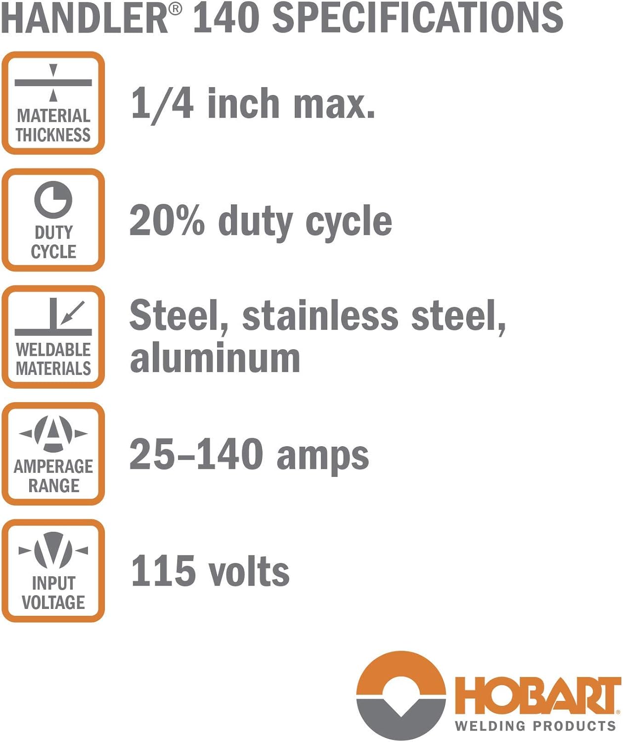
Figure 5.1: A specifications chart detailing the Handler 140's capabilities, including maximum material thickness, duty cycle, weldable materials, amperage range, and input voltage.

Figure 5.2: Illustration of the welder's arc performance, highlighting its ability to produce a smooth and stable arc for consistent weld beads.

Figure 5.3: An example of the Hobart Handler 140 being used for welding in an outdoor setting, demonstrating its portability and application versatility.
6. Maintenance
Regular maintenance ensures the longevity and optimal performance of your welder.
- Cleanliness: Keep the welder clean and free from dust, metal particles, and debris. Use compressed air to blow out the internal components periodically.
- Wire Liner: Inspect and clean the MIG gun wire liner regularly. Replace if it becomes clogged or kinked to ensure smooth wire feeding.
- Contact Tips: Replace worn or spattered contact tips to maintain good electrical contact and arc stability.
- Drive Rolls: Clean the drive rolls and ensure they are free of debris. Verify correct drive roll size and tension for the wire being used.

Figure 6.1: A close-up of the industrial-grade cast aluminum drive system, emphasizing its durability and importance for consistent wire feeding.
7. Troubleshooting
This section addresses common issues you might encounter during operation.
| Problem | Possible Cause | Solution |
|---|---|---|
| No Arc | Power switch off, poor work clamp connection, incorrect polarity, no wire feed. | Turn power on, ensure good work clamp connection, check polarity, verify wire feed. |
| Poor Weld Quality | Incorrect voltage/wire speed, improper gas flow (MIG), contaminated base metal, worn contact tip. | Adjust settings according to welding guide, check gas cylinder/flow, clean base metal, replace contact tip. |
| Wire Feeds Erratically | Incorrect drive roll tension, clogged liner, wrong drive roll size, kinked MIG gun cable. | Adjust drive roll tension, clean/replace liner, ensure correct drive rolls, straighten MIG gun cable. |
| Thermal Overload Light On | Exceeded duty cycle, insufficient ventilation. | Allow unit to cool down, ensure proper airflow around the machine. |
For more detailed troubleshooting, refer to the complete Owner's Manual.
8. Specifications
| Feature | Detail |
|---|---|
| Model | Handler 140 (500559) |
| Welding Processes | MIG (GMAW), Flux-Cored (FCAW) |
| Input Voltage | 115V AC |
| Input Amps | 20A |
| Output Range | 25 - 140A DC |
| Rated Output | 90A @ 18.5VDC, 20% Duty Cycle |
| Wire Size Capacity | 0.024 in. - 0.035 in. (Solid), 0.030 in. - 0.035 in. (Flux-Cored) |
| Material Thickness (Mild Steel) | 24 ga. to 1/4 in. |
| Material Thickness (Aluminum/Stainless Steel) | 16 ga. to 11 ga. |
| Item Weight | 57 pounds |
| Product Dimensions | 19 x 11 x 13 inches |
| Power Source | AC |
| Material | Steel, Stainless Steel, and Aluminum |
9. Warranty and Support
The Hobart Handler 140 MIG Welder comes with a 5-year limited warranty. For specific details regarding coverage and terms, please refer to the warranty documentation included with your product or contact Hobart customer support.
For technical assistance, parts, or service, please contact Hobart customer support. Contact information can be found in your Owner's Manual or on the official Hobart Welding Products website.

Figure 9.1: Hobart's commitment to quality and longevity in their welding products.


