1. Introduction
The Dwyer Magnehelic Series 605 Indicating Transmitter is designed for both visual monitoring and electronic control of very low differential pressure. This device is particularly suited for control applications within building HVAC systems, where local pressure indication is beneficial for routine maintenance and system troubleshooting. It combines the easily readable dial gauge of the time-proven Dwyer Magnehelic gauge mechanical design with Series 600 transmitter technology, providing a two-wire, 4-20 mA control signal. The rear terminal strip simplifies connection to any 4-20 mA control loop powered by a 10-35 VDC supply.

Figure 1: Front view of the Dwyer Magnehelic Series 605 Indicating Transmitter, showing the circular dial with pressure readings in inches of water, and the Dwyer logo at the bottom.
2. Safety Information
Please read and understand all instructions before installing or operating this product. Failure to do so may result in injury or damage to the equipment.
- Always disconnect power before making any electrical connections or performing maintenance.
- Ensure the power supply voltage is within the specified range (10-35 VDC).
- Do not exceed the maximum rated pressure or temperature.
- This device is designed for low differential pressure applications. Do not use for high-pressure systems beyond its specified limits.
- Installation and servicing should only be performed by qualified personnel.
- Protect the device from physical shock and excessive vibration.
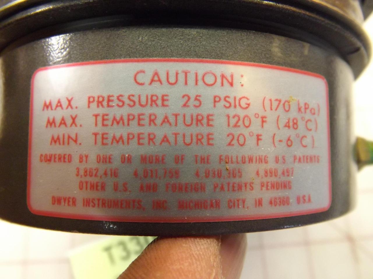
Figure 2: Close-up view of the caution label, indicating maximum pressure of 25 PSIG (170 kPa), maximum temperature of 120°F (48°C), and minimum temperature of 20°F (-6°C).
3. Product Features
- Dual Functionality: Provides both visual indication and electronic control of differential pressure.
- Application Specific: Ideal for HVAC systems and other low differential pressure control applications.
- Local Indication: Allows for easy visual checks during maintenance and troubleshooting.
- Output Signal: Standard two-wire, 4-20 mA output for integration into control systems.
- Power Supply: Operates on a wide 10-35 VDC power supply.
- Robust Design: Utilizes the proven Dwyer Magnehelic gauge mechanical design.
- Simplified Wiring: Features a convenient terminal strip on the rear for easy electrical connections.
4. Components and Overview
The Dwyer Magnehelic Series 605 consists of the following main components:
- Indicating Dial: Displays pressure readings in inches of water.
- Pointer: Indicates the current differential pressure on the dial.
- Zero Adjustment Screw: Used to set the pointer to zero when no pressure is applied.
- Span Adjustment Screw: Used for calibrating the output signal range.
- Pressure Ports: Two ports (High and Low) for connecting to the pressure source.
- Terminal Strip: For electrical connections (power and 4-20 mA output).
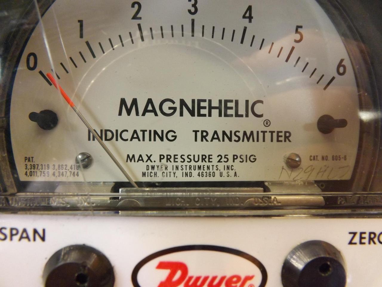
Figure 3: Close-up of the Magnehelic dial face, showing the "inches of water" scale, the pointer, and the "MAX. PRESSURE 25 PSIG" marking.

Figure 4: Detail view of the Dwyer logo, along with the "SPAN" and "ZERO" adjustment screws located on the lower part of the dial.
5. Setup and Installation
5.1 Mounting
The Series 605 can be surface mounted. Ensure the mounting location is stable, free from excessive vibration, and within the specified operating temperature range. Use appropriate fasteners for the mounting surface. The back of the unit features mounting holes for secure installation.
5.2 Electrical Connections
The transmitter utilizes a two-wire, 4-20 mA output signal. Connect the power supply and signal wires to the terminal strip located on the rear of the unit. Observe proper polarity.
- Connect the positive (+) terminal of the 10-35 VDC power supply to the appropriate terminal on the transmitter.
- Connect the negative (-) terminal of the power supply and the signal return to the common terminal.
- The 4-20 mA output signal will be present across the designated output terminals.
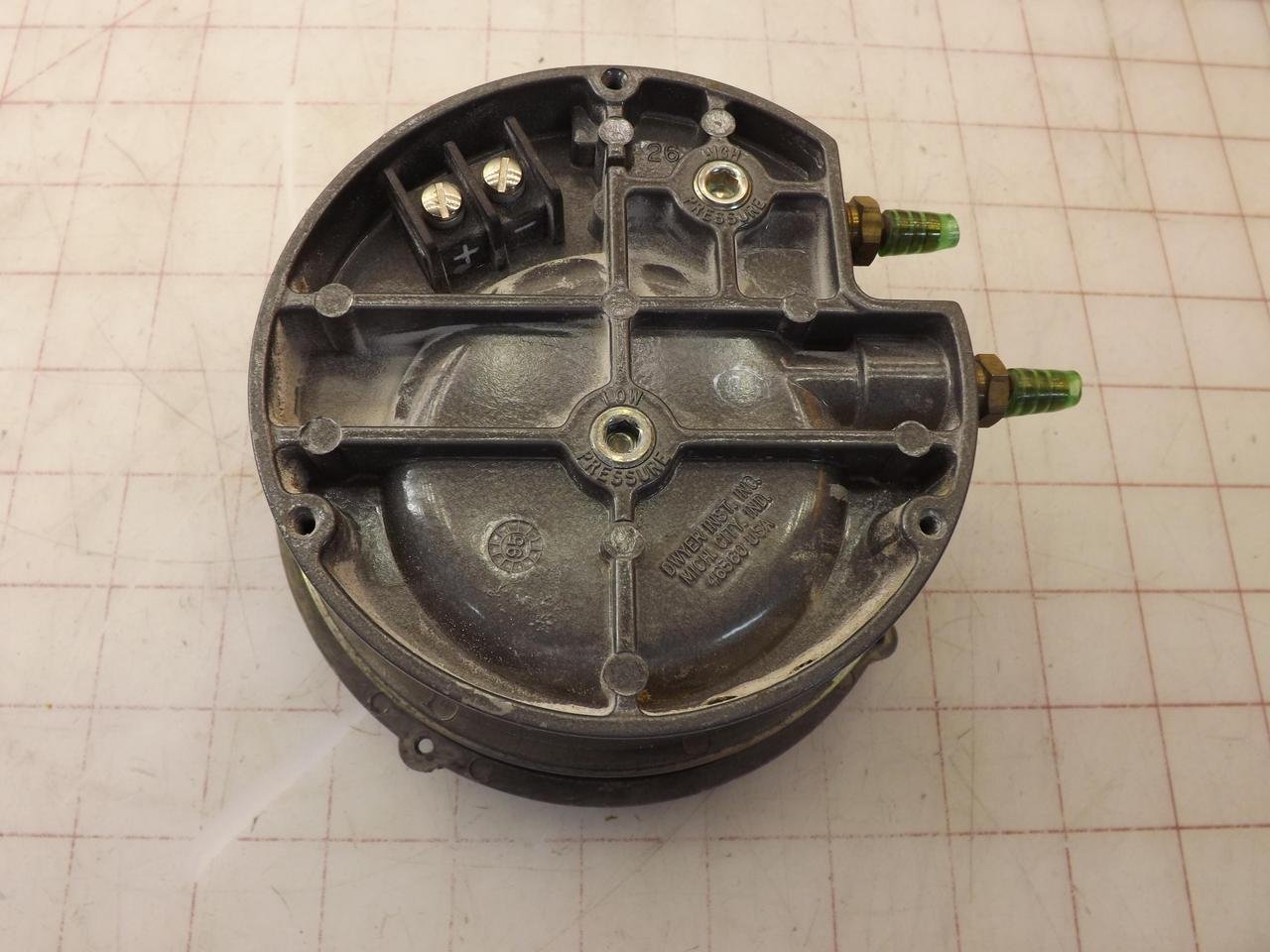
Figure 5: Rear view of the transmitter, showing the electrical terminal strip at the top and the high and low pressure ports with green caps.
5.3 Pressure Connections
Connect the high-pressure source to the "HIGH PRESSURE" port and the low-pressure source to the "LOW PRESSURE" port. Ensure all connections are secure and leak-free.

Figure 6: Side view of the transmitter, highlighting the two pressure ports with their protective green caps.
6. Operating Instructions
6.1 Initial Zero Adjustment
Before applying any pressure, ensure the pointer on the dial reads zero. If it does not, use a small screwdriver to carefully adjust the "ZERO" screw until the pointer aligns with the zero mark on the scale.
6.2 Reading the Dial
The dial indicates differential pressure in "inches of water" (WC). The red pointer moves across the scale to show the current pressure. Read the value directly from the scale where the pointer rests.
6.3 Span Adjustment (Calibration)
For precise 4-20 mA output calibration, apply a known full-scale pressure to the unit. Adjust the "SPAN" screw until the 4-20 mA output corresponds to the desired full-scale value (e.g., 20 mA at 6.0"WC for a 0-6.0"WC range). Refer to the specific calibration procedure in the full technical manual for detailed steps.
7. Maintenance
The Dwyer Magnehelic Series 605 is designed for minimal maintenance. However, regular checks can ensure optimal performance and longevity.
- Cleaning: Wipe the exterior with a soft, damp cloth. Do not use abrasive cleaners or solvents.
- Pressure Connections: Periodically check pressure tubing and connections for leaks or damage.
- Zero Check: Routinely verify the zero reading when no pressure is applied and adjust if necessary.
- Recalibration: Depending on application and environmental conditions, periodic recalibration of the 4-20 mA output may be required to maintain accuracy.
8. Troubleshooting
| Problem | Possible Cause | Solution |
|---|---|---|
| No pointer movement / No 4-20 mA output | No power, incorrect wiring, clogged pressure ports, damaged unit. | Check power supply (10-35 VDC). Verify wiring connections and polarity. Inspect pressure ports for obstructions. If issues persist, unit may be damaged. |
| Incorrect pressure reading on dial | Zero offset, span error, pressure leaks, incorrect pressure application. | Perform zero adjustment. Check for leaks in pressure tubing. Verify pressure source accuracy. Perform span calibration if necessary. |
| Inaccurate 4-20 mA output | Incorrect calibration, power supply issues, load resistance too high/low. | Perform span calibration. Ensure power supply is stable and within range. Check load resistance in the control loop (typically 250-750 ohms). |
9. Specifications
- Model: 605-6
- Range: 0-6.0"WC (Inches of Water Column)
- Output: 4-20 mA, 2-wire
- Power Supply: 10-35 VDC
- Max. Pressure: 25 PSIG (170 kPa)
- Max. Temperature: 120°F (48°C)
- Min. Temperature: 20°F (-6°C)
- Dimensions: Approximately 7.6 x 6.1 x 3.2 inches
- Weight: Approximately 2.29 Pounds
- Manufacturer: Dwyer Instruments
10. Warranty and Support
For information regarding product warranty, technical support, or service, please contact Dwyer Instruments directly or visit their official website. Ensure you have your product model number (605-6) and serial number (if applicable) ready when contacting support.
Dwyer Instruments, Inc.
Michigan City, IN 46360 U.S.A.
For the most up-to-date contact information and resources, please refer to the official Dwyer Instruments website: www.dwyer-inst.com